ENGINE BUILD CLASS CHAPTER
To read another Chapter click hereunder:
This chapter is only dedicated to our XP-360 manufacturing trip to Jade Air in St. Neots UK.
We are in St. Neots with a lot of people from Sunday, January 14th to Friday the 19th.
With me and Elvira, Joeri and Dimitri, our sons, are accompanying us. Debby, Dimitri's girlfriend will join us at Tuesday.
Next, Ronny of course, is also here as my airplane project sparring partner. He will also follow the building class. On Monday, Gerry is also coming over to join the building class.
The planning is as follows: Elvira, Joeri and later also Debby are going to spend their time in another way. The two girls will shop and afterwards going for shopping. Once they don't know anymore what to do, they will try to find out how they can do some more shopping... So, no problem at all. I think they will enjoy their stay... Joeri has other plans... Instead of spending money, he will visit some prospects to have an introduction talk for his software. He is trying to find dealers for this product. By the way, a beautiful and very performant automation software for those who dream from automated publishing... If you are interested have a look at his website. There are some nice demo's available of it's possibilities.
And then, more project related, the building class that Jade Air will give us...
Derek Graham from Jade Air gave me the following programm for the coming days.
Monday, January the 15th:
we will inspect all parts and walk through the manuals
Tuesday, January the 16th:
Building the engine
Wednesday, January the 17th:
Building the engine
Thursday, January the 18th:
Testrun and crating the engine
Friday, January the 19th:
building class finished, we plan to visit the airmudeum of Duxford...
So, enjoy... I will try to provide this page with pictures showing the complete assembly and building class.
| Monday, January 14th, 2007 | Assembly part I |
| The location I choosed was JadeAir in St. Neots UK. And, to be hounest, this was really the best choice I could make. What an experience... In this Chapter I would like to try to give you an impression of the assembling of an XP-360. Based on our experience and the information we gathered. And on top of that, illustrated with a lot of pictures showing the three day building class we had. I hope you will enjoy it and more, that you will find the motivation to follow this adventure... Here it starts. Normally you start in the building class with a lot of inspection tasks, cleaning, making an inventory... But, this was already done by the people of Jade Air before our arrival. Every part inspected, listed and sorted to start immediately with the assembling. Let's hace a closer view to the parts... |
|
| The major part of the engine, the two halves of the crankcase.We inspected the surface for burrs at spli lines,we had a close look to the cam bores and we verified the finish. To be short, a close look and check for possible handling damage...
Beside the crankcase you can see the starter. |
|
| Next the 4 pistons. These are real masterpieces when you see them lying there. | |
| This is the identification that the trolley contains with all the parts for the engine I bought. My XP IO 360 BIAAZ engine in thousand pieces... Thrilling.... | |
| And then, a lot of bolts, nuts, washers and until that moment for me Unidentified Small Things... (UST's) | |
| A carton bow with all kind of gaskets en the covers for the cilinders... | |
| And again, a masterpiece, a real piece of art, the crankshaft... | |
| Here you see some gears, the piston pins and a lot of UST's more... | |
| The place where it happens is a clean and well organized factory. | |
| Well, I can go on butas you can see in the following pictures, there are a hell of a lot parts to be assembled. But so far, most of them remain ULT's. They will be identified during the building process... | |
| Dimitri took all these pictures of the Jade Air facilities to give an impression of the way these guys are working. Clean, professional, inviting for technology-interested people... | |
| This is the place where it will happen. Everything ready to start... | |
| And this guy is the engineer who will build up the engine with us. David Ash is his name. So far I can tell you that he has a memory full of experience. All torque values coming straight from his head without looking in manuals... And, very calm and communicative... | |
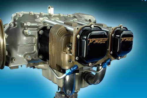
| And then we started. The start of the process is the assembling of the accessory housing. This holds the oil filter adapter, the oil pum gears, the tach drive mechanism, the oil breather. | |
| Here David starts with the iinstallation of the oil pump drive shaft . | |
| The edges of the oil pump housing are provded with pre lube before it is attached to the accessory housing. | |
| The oil pump gears where brought in place and, very important, everytime a drop of oil accompanied the parts... | |
| The oil pump housing closes the gears off by bringing it over the studs. Afterwards, before torqueing the bolts, first a smooth rotation is tested of the gears. Possibly the housing has to be twisted a little to achieve that smooth rotating of the pump drive shaft. Then, at least the complete assembly is torqued to 17 ft/inch... | |
| And again the smooth rotation is tested... | |
| So far so good... Up to the next step... | |
| Installation of the oil filter adapter.
First we installed the stud in the accessory housing to a driven height of .60” to .65”. Then we applied a light coat of grease to threads. For that we used the installation tool, SLT 25C. |
|
| We installed a light coat of Dow Corning #4 lubricant or something equivalent to rubber seal at base of spin-on oil filter and lightly lubed the filter threads, then installed to oil filter adapter and torque in accordance with EO 242 “Table of Limits, Torque Limit Table”. Finally we safety wired oil filter to adapter. |
|
| Bolts torqued with 69 inch/pound. It is in this part that the oil temperature sensor will be placed. David told that this is the first place you have to look when oil temperature problems occur... The bolts where torqued 21 foot/pound. | |
| Next thing was to separate the two halfs of the engine block. A lot of man (arm)-power is needed to separate these two parts. This has to be done very carefully to avoid any possibility for damage. | |
| In the meantime the most important pieces of the accessory housing are installed. | |
| With both case halves on the bench we verified the surface finish and absence of burrs at the split lines, bearing and cam bores, mating surfaces and tappet bores. We checked again for handling damage. Then we inspected the studs for thread damage, bent condition. |
|
| Especially the differences and the improvements in comparison with the traditional Lycoming engines were showed.
We inspected the oil galleys in each case half to insure they are clear and clean and that they properly intersect. Clean, dry air was blown through each passage as a useful aid for this inspection. |
|
| Check front main bearing retention dowel installation for correct height. (.070”-.090”)
David applied a light coat of pre-lube oil to bearing shells and install “bare” crankshaft in 1-3 case half. Check thrust and slinger clearance per EO 242 “Table of Limits, item #5, Crankshaft Main Bearings” and record clearances. Rotate crank 360 degrees to insure adequate “cheek to case” clearance. We repeated this process in 2-4 case half and record thrust and slinger clearance. |
|
| We lightly lubed each cam bore journal and rotate camshaft in each case half. Measured and recorded end clearance in each half per EO 242 “Table of Limits, item #9 Camshaft Journal”. Then we examined the tapped threads and installed proper plug and cylinder drain nipples in each location using an appropriate thread sealant (Tite-Seal or equivalent) and torqued I/A/W EO 242 “Table of Limits, Torque Table”. |
|
| The little piece on the left side is the part which holds the gears for the crankshaft. These are the Idler shafts which are torqued with 17 ft/lbs. The bolts are secured with safetywire. | |
| With both halves open, David gave us a sight seeing tour inside the engine. The trip brought us to all campartiments like the oil galleries and all the small but important corners an engine has...
Next we installed the one half of the engine to a stand on which we will continue to work. |
|
| In one half of the engine, two studs were placed. These studs will hold both halves in place. And then... | |
| We inspected the bearing tang slots for deformation and installed the main bearings in case halves, except for the front main bearing.
You can see the bearings installed where the cranckshaft will come. Nect the pushrods were put in place to protect the oil gallery to be affected with loebe or dirt. |
|
| While the crankshaft nose seal was put in a heating device (necessary to stretch it over the crank propellor flange), David started with some hocus pocus things. He explained that sealing both halves of the crankcase has to be done with a thin silk wire. That procedure is showed in the following pictures.
To start, the edges where provided with the loebe that had to "dry" for one hour... |
|
|
Fisrt we assured that case mating surfaces were clean and dry. Then David applied an even, thin coat of approved sealant to the backbone and breastbone surfaces of the 2-4 case half only and to the front nose seal bore (both case halves) as well as the nose seal (When using RTV 102, the coating must not be too thick. |
|
|
A thin translucent coating, wiping off any excess on the inside and outside edges, is sufficient. See previous picture. Because this sealant will dry quickly when applied this thin it is important to move along quickly until case halves are together and snugged. A helping hand is required during this assembly process.
|
|
| Next thing was the installation of the cranckshaft. This big plate in front is the frontside of the engine... The place where later the hub for the propellor and the propellor will be installed... It is called the crank prop flange. |
|
| This is the position where the crankgear has to be installed. You can see the result later in the pictures. | |
| To do this, first we had to inspect the crank gear, the accompanying bolt and lock plate for defects. | |
| Notice the diameter of the crank prop flange and the seal. The seal had to go over this flange. And that is why David put it in a heater to make it more stretcheable...
David warmed it up and used a special tool. This is rather critical to do. That's why it had to be warmed up. |
|
|
PROCEDURE: 1) Remove spring from seal. |
|
| At the end, this must be the result.
Be carefull. This is a critical part and possible oil leaks first appear here. This is what we saw after the engine testrun. It had to be done over again to seal the leak... |
|
| We lightly lubed the crank bolt threads, and installed the gear to crankshaft with bolt and lockplate. Insuring that the gear fits evenly in crank recess, aligns with dowel and sits flat when torqued. Tapping gear with a soft aluminum or brass drift will help insure the gear is properly seated. Attempt to insert a pointed .001 inch feeler gage or piece of shim stock between the gear and the crankshaft at each of the three scallops. There is no allowable clearance between crankshaft and gear. We torqued the bolt I/A/W EO 242 “Table of Limits, Torque Limit Table” and bend lock tab up to secure bolt head. | |
| Here a better view of the way the gear is mounted and secured on the crankshaft... | |
| The gear was installed on the cranckshaft and secured internally with the securing plate. The gear was torqued with 17 Inch/foot. |
|
|
Next step in the assembly was to verify correct rod part numbers. Then verify the serial number match for each rod and cap assembly. Then verify and record the rod weights. Visually inspect for handling damage, defects and/or corrosion. Inspecting bore finish to be smooth and free from burrs. Verify connecting rod bushing installation. Check piston pin in each rod for fit. |
|
| An overview of the bearings and the conrods. | |
| The conrods are numbered. As a method to recognize later where they have to be installed, all these conrods are numbered with a unique number. The lowest number will most frotward be installed.
Conrod positions: 2 = number 4021 3 = number 4065 4 = number 4142 Torqued with 40 ft/Lbs |
|
| And then the connecting rods to crankshaft subassembly could start...
We layd out and visually inspected the rod bolts and nuts and lightly lubed the bolt shank and threads with pre-lube oil. |
|
|
... and then installed the connecting rod bearing shells in each rod and cap. We applied pre-lube oil to bearing shell, applied pre-lube oil to rod bearing journals of crankshaft. And finally inserted 2 ea. rod bolts through the rod cap with lowest serial number and installed it to the crankshaft with matching rod at the #1 (forward most) rod location. |
|
|
This was repeated for all sets and then we torqued each rod bolt and nut evenly, I/A/W EO 242 “Table of Limits, Torque Limits Table”. |
|
| Finally we checked the rods for a smooth, free spin fit. Measure and record side clearance. Reference EO242 “Table of Limits, Item # 4, Connecting Rod.” | |
| After all conrods and bearings where installed, a colleague of David checked all torques and the installation. A matter of Q... | |
| One hour further: back to the loebe "painted" half of the engine. On the loebe, a small wire of pure silk was placed (see pictures). This will act as a gasket. Reason, it is very thin. It is heat resistant and once the two hlafs of the engine are torqued together, the silk wire becomes extremely thin but almost 2 mm wide. | |
| A single line of silk thread on the RTV sealant at the centerline of the sealing surface and looping the inside of each bolt hole was done. The tail of the thread should extend beyond the mating surface approx. 1⁄4” to the accessory gasket surface at the rear, the nose seal surface at the front and the sump gasket surface at the bottom. | |
| Here some pictures of this technique... | |
| We installed two 3/8” bolts with their corresponding flat washers through the 1-3 (right) case half and install 2ea. O-rings.
Then we installed 2ea. O-rings on rear through studs of 1-3 case half. |
|
| The second half of the engine received the camshaft which is hold in place with a wire. This to keep it that way when the two parts are brought together... | |
| The crankshaft receives some oil to seal better in the bearings when the two halves are brought together. | |
|
Before bringing the crankshaft in the other half, we had to check the thread and nose seal for proper placement. Install the camshaft in 2-4 case half as shown in previous picture, Mate the 1-3 case half to the 2-4 case half by carefully aligning rear through studs and front 3/8” nose bolts. NOTE: Care has to be taken not to push out the 3/8” nose bolts causing the O-rings to fall out. Install the backbone, breastbone and nose bolt hardware and snug all uniformly and check for free case/crank rotation. |
|
| After putting graphite grease and all necessary loebe, it is ready to receive the second half... | |
| Insure that the nose seal is properly in place. | |
| Measurements where made to bring the parts in the correct position.
A space of 0,305 mm is measured and tuned between the crancks and the engine body 0,127 mm on the front where the rubber ring is and .102 mm between the gear and the engine. |
|
| Liightly lube the shank and threads of the 1/2” diameter. through studs, P/N SL76220, with pre-lube oil ... | |
| Then the two parts are pressed verey securely together... | |
| And finally install with a soft faced (dead blow) hammer in crankcase. | |
| After putting the drop of oil on each bolt. Temporarily they are torqued with 40 ft/inch. Later in the proces they will be finally torqued to 50 ft/inch. The two nose bolts are torqued 25 ft/inch... | |
| To mount some parts of the ignition system, the manual is being sudied... | |
| All bolts bolted and torqued and the three inner bolts on the bottom receive castle nuts that were secured with safety wire... The castle nuts are torqued ith 96 inch/Lbs. | |
| Next are the gears for the cranckshaft and the camshaft. These have to be tuned for the right moments. With the first cilinder up, all gears need to correspond over the zeros indicated on the gears... | |
|
First we had to place the left-hand idler gear (fuel pump drive idler gear) over the left idler shaft aligning its timing marks with corresponding timing marks found on camshaft and crankshaft. Then rotate the camshaft and crankshaft as needed to align with marks on the idler gear. |
|
| We installed the right hand idler gear on the right side idler shaft and checked gear backlash of both idler gears with “feeler” gauge or dial indicator I/A/W EO 242 “Table of Limits, Gear Teeth Backlash Table”. | |
|
We next installed the tachometer shaft assy with retaining ring in the camshaft at gear end. |
|
| The rod you see here is part of the tachometer shaft. A RPM cable connected to this shaft will bring the RPM of the engine to any mechanical gage. Because we will get that information from the magnetos, David took them out again. Reason is that there is always a risk that the clip will loose and some normal metal parts can affect the oil. Due to the faxt that I will install the Dynon EMS, this can be taken out... Additional advantage: weight gain... The accessory housing block was next installed with a torque of 96 inch/Lbs. |
|
| These are the parts David took out... | |
| Here the accessory housing block. | |
| On top you see some extra loebe to seal the connection in a better way... | |
| Later, torqued with 96 inch/Lbs... | |
| Next is the light weight sump to be installed. The pick-up strainer is installed in place. This is the first filter that keeps the oil clean before it will be sucked into the galleries... | |
|
We first lubed the governor shaft gear and bore in adapter with pre-lube oil and installed the shaft gear in adapter. Then we placed the thrust washer on the shaft gear and secured the shaft gear in the adapter with a snap ring. We insured free spin of gear in adapter and check end clearance per EO 242 “Table of Limits, Gear Teeth Backlash and End Clearance”. |
|
|
Then we installed the adapter assembly to accessory housing with associated gasket and hardware and torqued I/A/W EO 242 “Table of Limits, Torque Limit Table”. We checked the gear lash per EO 242 “Table of Limits, Gear Teeth Backlash and End Clearance”. |
|
| A tip... Such thrust shers have two sides. A sharp edged side and a soft siide. The sharp side always be the outside... | |
|
We lightly lubed the threads of the 45° elbowand its We applied Tite-Seal thread sealant to the threads of the 90° elbow and installed them in the right crankcase half, forward of #2 cylinder. We positioned the fittings ready to install later the propeller governor oil hose. (To be tightenend I/A/W “Table of Limits, Torque Limit Table”). |
|
| And finally for today, the fuel pump was installed. We applied pre-lube oil to threads of 90° elbow and O-ring and installed them into the fuel pump outlet port. Positioned elbow to correct orientation and torqued lock nut in accordance with EO 242 “Table of Limits, Torque Limit Table” We applied pre-lube oil to threads of 45° elbow and O-ring and installed them into fuel pump inlet port. Positioned elbow to correct orientation and torqued lock nut. Next applied grease to fuel pump arm and plunger where they will make contact (wear surfaces). We installed the fuel pump with gasket and 2 each 3/8” drilled, socket head screws and flat washers. |
|
| Tuesday, January 15th, 2007 | Assembling the engine II |
|
We verified the magneto part numbers and serial numbers per pick list and then installed the drive gear to magneto by removing the gear retaining nut and washer from magneto and installing drive gear with washer and nut. |
|
|
Torqued the nut in accordance with installation instructions provided by Unison and secure with cotter pin. Repeated this for the 2nd magneto. Then we installed the magneto gasket and spacer to the accessory housing at each magneto location. David removed the harness cover cap from each magneto. |
|
| He determined the direction of rotation. Refer to magneto data plate. | |
|
An alignment pin was inserted in appropriate hole “R” or “L” in magneto, as determined by the direction of rotation, and slowly rotate magneto drive shaft “backwards” until alignment pin drops into position (to the first shoulder), locking the shaft. NOTE: While rotating magneto shaft backwards, with alignment pin in hole, if it stops turning due to internal interference against the alignment pin prior to pin “seating”, pull pin out, just far enough to allow shaft to continue to rotate, then re-insert pin, and continue rotation until pin seats as previously described. This procedure locates the magneto at the #1 cylinder firing position. |
|
|
We repeated this for the 2nd magneto. |
|
|
David brought the engine to the compression stroke on #1 cylinder by rotating engine with one spark plug hole plugged and the other covered by a thumb or finger to feel air pressure during the compression stroke. |
|
| Pre-lube oil was applied to idler gear teeth and magneto drive gear teeth and light coat of Dow Corning #4 or Fuel lube was applied to the magneto gasket before installing each magneto with appropriate hardware and snugged moderately. NOTE: Magnetos must be able to move for final timing. This will be accomplished later, with the engine horizontal, disconnected from nose stand and with ring gear and starter installed. |
|
|
We stimated 25° before top dead center with a timing indicator installed in a spark plug hole of #1 cylinder or equivalent method. |
|
| Then we verified the part number and serial number of fuel injection unit (servo) with pick list. We installed the servo to the sump with the appropriate gaskets, spacer and hardware and torqued the attach nuts in accordance with EO 242 “Table of Limits, Torque Limit Table” |
|
| . Install the manifold (flow divider) bracket to the flow divider, with 4 each screws and lock washers. Torqued screws in accordance with EO 242 “Table of Limits, Torque Limit Table”. |
|
| Installed the flow divider and bracket assembly to the engine backbone (top) and torque attach hardware in accordance with EO 242 “Table of Limits, Torque Limit Table”. NOTE: Removed and re-install appropriate backbone hardware to accommodate bracket and install bolt with lock washer. |
|
| Applied anti-seize to 4 each fuel injection nozzles and installed in cylinders. Torqued the injection nozzles in accordance with EO 242 “Table of Limits, Torque Limit Table”. |
|
| Installed fuel lines between fuel injectors and flow divider (manifold valve) and clamped them. Tightened lines in accordance with EO 242 “Table of Limits, Torque Limit Table”. |
|
| Wednesday, January 17th, 2007 | Assembling the engine III |
| We installed the fuel injector fittings, appropriate pipe plugs and nipples into the flow divider. Used anti-seize on male threads and torqued in accordance with EO 242 “Table of Limits, Torque Limit Table”. |
|
| Installed #6 fuel hose between fuel pump (outlet) and fuel servo (inlet) and #4 fuel hose between fuel servo (outlet) and fuel flow divider (inlet). Torqued per EO 242 “Table Of Limits, Torque Limit Table”. |
|
| After removing the timing locator pins from magnetos we installed the harness insuring right harness on right magneto and left on left.
The cap was aligned properly and secure with screws provided from cap removal. Tightened in accordance with EO 242 “Table of Limits”. |
|
| Wednesday, January 17th, 2007 | Engine to Testbed and first testrun |
| #e6e6d7 | |
| Here you can see and hear the first test run of the engine. It was ran the first time at about 1:44 in the afternoon. After some starting without ignition (to set the oil around in the cilinders, it started up after two trials. Enjoy... | |
To continue reading the following or previous chapter(s), click on the Chapter hereunder...