OVERVIEW OF GOOD-TO-KNOW TOOL AND BUILDING INFORMATION
1 - General information
WHAT TOOLS DO YOU NEED TO BUILD AN AIRPLANE...It is best to refer to the building manual provided with the kit. It should provide a recommended tool list. If you do not locate the list, check with your kit supplier. Several tool suppliers designed an RV toolkit using the Van's Aircraft list. This list can be found mostly on the supplier's websites. I refer to the link-pages where several tools suppliers are listed.
DO YOU REALLY NEED EVERYTHING THESE SUPPLIERS PROPOSE??
No, you do not absolutely need every item included in a supplier's lists; however you should try to have all of the tools the kit manufacturer recommends. Remember -- not having the right tool for a job can make the task much more difficult and time consuming, and may result in added frustation and sub-standard results. First, look around in the supplier's shop -- you may already have a few of the tools needed. You could start with the basics -- a rivet gun, a few rivet sets, a bucking bar; and add the rest of the tools as you find a need for them and can afford them. Keep in mind that all showed catalogs and the tool kits are full of items that are great time-savers and frustration-preventers. The best advice is to go out and talk to people who are building or have built a project like yours, and see what they experienced. A helpful tip is to order some literature and/or information videos about this topic.
MEASURING AN BOLTS
Do AN bolt length “--numbers” confuse you?? Here is the secret to how to measure bolt lengths with a scale. AN BOLT LENGTHS ARE MEASURED IN INCREMENTS OF 1/8”. Example: a -4 length is 4-8ths, or 1/2”; a -6 is 6 - 8ths, or 3/4”; & a -7 is 7/8”. Note that after a -7 the next size is a -10; this bolt would be 1” long. At 1” the 2 digit -- numbers start. You now read the first number as full inches & the second number as fractions of an inch in 1/8ths. Example: a -13 length is 1 & 3/8”; a -25 length is 2 & 5/8”; a - 34 length is 3 & 1/2”. Note this length is measured from under the bolt head to the end of the threads. Also, note that bolt diam-eters are measured in 1/16ths. A -3 diameter is 3/16”; & a -4 dia. is 4/16 or 1/4”. SIMPLE GRADE SCHOOL FRACTIONS !!!!!!
PUNCH USE
If you have a rivet that will not go in a hole, use a punch to align holes in mating parts — just insert the punch in the hole and twist around in a circular motion and this will pull the parts together in alignment. If the rivet is still tight, you can repeat with a little more circular force and the punch motion will actually enlarge the hole slightly -- (practice this slowly so you don’t oversize the hole).
When removing rivets drill into the rivet head to a depth equal to the height of the head (caution — any deeper may damage the hole in the part) and use a punch the size of the drill to break or snap off the rivet head; then drive the rivet shank out with the punch. You may need to back up the rivet when punching it out -- a simple method is to use a block of wood or plastic with a drilled hole large enough for the rivet shank to fall into. The block supports the area around the rivet + does not mar the surface; however, this may take an extra hand to accomplish.
HOLE REAMING
Always use a lubricant when reaming holes. Use a slow turning drill (electric of cordless drill). Start with about a 1/32" undersize hole and finish ream to the desired hole size. Hold the drill and reamer square. To make a temporary drill or reamer guide for holes in parts that cannot be taken to a drill press, first drill or ream a guide hole in a block of material (wood, aluminum, plastic, etc.) and clamp the block onto your work -- you now have a true & square hole guide.
2 - Air compressor and related topics
AIR COMPRESSOR
For most air tools used to build an airplane kit a 2 to 5 H.P. portable piston type air compressor is adequate. The main consideration is the CFM (cubic feet per minute) rating of the compressor. Most air tools will use 4 to 5 CFM at 90 PSI under continuous use. You will want a compressor that supplies a minimum of 5 CFM at 90 PSI. (Note: some compressors give CFM ratings at lower PSI pressures -- don't be fooled by a 4 or 5 CFM rating at 30 or 40 PSI). Also pay attention to the wattage or current draw of the motor -- a more energy efficient motor will pay for itself over the life of the project. Consider a 220 volt motor if electric service is available in your shop. If you plan to paint your airplane, and for continuous use tools (die grinders, sanders, paint guns) get a larger (6-8 CFM) compressor to avoid running out of air, waiting for pressure recovery, and over-heating the compressor. A special consideration here: Air compressors are designed to run a cycle and be off a sufficient time to avoid over-heating of the compressor cylinders, pistons, oil, valves, etc. If you get too small a compressor and run it continuously, it will over-heat, wear out quickly, and contaminate your air hoses and tools with burned oil and carbon particles, air hose rubber particles from deteriorating hoses, etc. (I've repaired a lot of air tools over the years and seen it all!!). Tank size determines the amount of time the compressor runs to fill up the tank -- so get the biggest tank you have room for. Last, check out how much noise the compressor makes when starting up & running before you buy it. If it's in the garage with you or outside next to the neighbor's bedroom, the noise level might be a big factor.
WHAT SIZE AIR COMPRESSOR DO YOU NEED?
For most air tools a 2 to 5 H.P. portable compressor is adequate. Check the CFM (cubic feet per minute) rating of the compressor. Most air tools (drills, die grinders, rivet guns) are rated from 2 to 6 CFM for continuious use. Keep in mind that you will not be drilling or riveting for long periods. So the compressor will not need to run continiuously. The exception is if you plan to paint your airplane -- get a compressor big enough to suppuly continious air supply for the paint gun you plan to use.
HELPFUL AIR TOOL TIPS
Air tools should be oiled daily when in use with a non-detergent type oil . 4 or 5 drops of air tool oil, or Marvel Mystery Oil, through the rear air inlet of the tool is recommended. If possible, a fog type oiler is recommended. Check your air compressor daily for excess water, and drain as necessary. Moisture greatly affects and reduces tool life and efficiency.
120 P.S.I. is maximum satisfactory pressure for most air tools, consult the mfg. specifications. Store your air tools in a clean and dry place when not in use. Also, cover air inlets and rivet gun barrels to keep bugs and foreign matter out. Lubricate and run air tools frequently to avoid corrosion and gumming of lubricants.
3 - Rivet Gun and related topics
WHAT IS THE DIFFERENCE BETWEEN A 2x / 3x / 4x RIVET GUN?
The only outward difference is that the 3X gun has a barrel about 1/2" longer than a 2X gun. Inside, the 3X gun has a longer stroke and a heavier (longer) piston; thus it hits fewer strokes per minute but is harder hitting than a 2X gun. The 2X gun has a shorter stroke and a lighter (shorter) piston and while it hits more blows per minute (because of the shorter stroke) the lighter piston does not hit as hard, thus it is easier to control. Either the 2X or 3X guns will work for setting 3/32" and 1/8" rivets and the air pressure used can be adjusted up or down to each individuals liking to make either gun seem to hit harder or softer. Note the 4X gun is just bigger (longer) than a 3X gun and has a 1/4” rivet capacity.
Tip: Check with local builders / mechanics and try out the different size guns before you order.
WHICH RIVET GUN DO YOU NEED, A 2x or 3x?
Both the 2X & 3X guns will set 3/32" & 1/8" rivets. The 2X gun has a shorter stroke and shorter (lighter) piston, and hits more blows per minute -- the blows are lighter than a 3X, thus it takes longer to set a rivet with a 2X gun. The 3X gun has a longer stroke and longer (heavier) piston, and hits fewer blows per minute -- the blows are heavier than a 2X, thus it takes a shorter time to set a rivet. Keep in mind you can regulate your air pressure up or down to make either a 2X or 3X gun hit harder or lighter.
Suggestion: Contact other builders in your area and try out both a 2X & 3X gun -- choosing a rivet gun can come down to a personal preference of how a particular gun feels to each individual.
CAN YOU USE AN "AIR HAMMER/CHISEL" IN PLACE OF A RIVET GUN?
Air hammer/chisel guns are designed for hitting hard and do not have a teasing trigger like a rivet gun. The results will not be good.
Suggestion: Find another builder in your area with a real rivet gun -- set some rivets with a real rivet gun and some with a muffler cutter and compare the results.
RIVETING TIPS
When riveting with a universal rivet set you may experience marks on the head of the rivet from time to time. An old riveting trick is to put one or two pieces of masking tape on the end of the set (sticky side into the cupping) and this will usually help cushion and protect the rivet head. Note the tape will have to be replaced every 4th or 5th rivet as the tape wears out. Also, a piece of masking tape put on the face of a flush rivet set will keep the set from leaving black marks on the surface of the work. This tape will have to be replaced periodically when it wears through.
Notes on Good Riveting (Article Sam Richards on vansairforce.net)
Preparation:
- Materials deburred on edges;
- Holes laid out in correct locations, taking into account pitch and edge distance requirements
- Holes centre-punched using a backing plate to avoid sheet distortion;
- Parts assembled securely together and supported while being drilled with a sharpened bit of the correct size. Holes drilled squarely to
surrounding surface.
- Parts disassembled and holes deburred;
- Holes dimpled or countersunk if accepting AN 426 Flush head rivets.
- Parts reassembled and clecoed;
- Selection of new AN rivets of correct diameter and length;
- Assembly well secured in a vice, a jig or on a workboard.
Tips:
- Before beginning a new phase, try rigging a test piece or a component mock up. Cardboard mock ups will conserve material and will help to obtain correct sizes and shapes.
- Setting the first rivets of the day should be done on a test piece to ensure proper air pressure; tool adjustment; and operator currency.
- Place masking tape on rivet sets to stabilise them while riveting. (renew frequently)
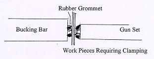
- A rubber grommet placed over the rivet tail will compress components together ensuring a close joint as riveting progresses. Use where clamps or clecoes are impractical.
Rivet Gun
Rivet gun should be lightly oiled (air port and inner shank of set) daily before work commences. Set should be securely attached with retaining spring in place. It should then be tested on a firmly secured piece of wood. This will confirm its operational status and will alert the operator to any alterations necessary (change in air pressure; wrong size set, etc).
A rivet gun should not be fired:
- without a set secured by a retaining spring
- without an intended target firmly in place against set and without ear and eye protection
A rivet gun should be disconnected from the air source when:
- Sets are being changed
- Maintenance is being carried out on gun
- Gun is not being used
Gun set
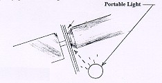
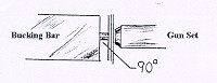
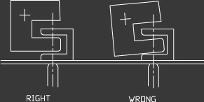
Rivet gun set is correct for the size of the rivet and is positioned at 90 degrees to the work surface. With universal rivet sets, the reflection of the gun set in an aluminium surface will give the impression of a continuous straight line with the gun set itself if positioned at 90 degrees. Also, light reflecting from the edge of the rivet head will appear as an even line around a properly positioned gun set.
Bucking bar orientation
1. Rest bucking bar on inserted rivet and try to locate its point of balance.
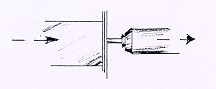
2. With gun set in place, use bucking bar to push rivet (and gun assembly) outward. Bucking bar will then register at right angles to the rivet as it comes to rest on the aluminium.
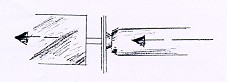
3. Push rivet back into place with gun set and reposition bucking bar, if necessary, to maintain its point of balance on the rivet. (repeat steps 2 and 3 until point of balance is determined). Often the index finger can be placed on the back of the bucking bar directly opposite the rivet tail. It then becomes the 'sensor' for correct bar position.
4. Pressure is held on gun while riveting. Bucking bar is held with only moderate force (otherwise rivet may be set with head proud of surface). A rubber grommet may be used over the rivet tail to assist in squeezing parts together during riveting. It acts as a 'pressure plate'
5. Duration of riveting is determined by experimentation with a test piece or previous experience.
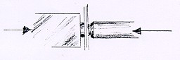
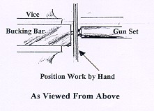
Bench Riveting
Often components are more easily riveted as sub-assemblies (off the airframe). A workbench allows components to be positioned and secured optimally for joining.
The bucking bar may be secured in a bench vice and, with the components positioned by hand, rivets are set with a gun held in the other hand. The main advantage here is that the bar is stationary and the components may be more easily held and positioned for riveting.
Back Riveting
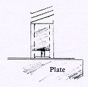
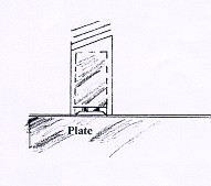
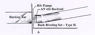
Back riveting is a method of setting rivets, usually in a skin component, by striking the buck tails with a special gun set while the flush head is securely supported in its dimple or counter sink by a steel plate or bucking bar.
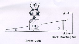
Control surfaces are usually back riveted using a horizontal steel plate mounted on a table. The skin rivets are held vertically in their holes with thin Scotch Magic tape or fine Mylar tapes over the heads. The internal rib or stiffener is placed over the rivets and the special gun set is used to sequentially set these fasteners. Note: try using all RV-Workshop Learning centre back riveting sets.
Type I
Type II
Type III

If the builder is working alone, sometimes it is difficult to judge when the backriveting set/gun is square to the surface being joined.
Solution:
- Using shims, level the back riveting plate on the table.
- Using a drill press, drill a half inch hole almost through a 4" x 4" x 2" piece of hardwood.
- Mount a straight universal head rivet set in riveting gun.
- Use Vaseline to push the end of the set into the hole in the hardwood.
- Place the hardwood on the levelled surface plate so that the gun is supported vertically.
- Secure a round bubble level vial to the butt of the rivet gun with RTV or a silicone adhesive.
- Make sure the vial is positioned so that the bubble is in the centre.
- Secure the assembly so that it cures in that position overnight.
This will aid in setting perfectly aligned rivets provided
- The back riveting plate is levelled prior to use;
- The gun is held with the bubble in the centre while riveting.
Note: It pays to periodically recheck calibration using the wood block and straight rivet set. The straight set is only used during calibration. The back riveting set is reinstalled for actual riveting.
Riveting with a Partner
There are places on RVs which cannot easily be riveted by one person. Main wing skins are a good example. This becomes a two-person operation, with one bucking and one riveting. The principles of good riveting are exactly the same, the only variable introduced is the co-ordination of two workers (and the advantage of two extra hands). As the partners cannot see what the other is doing, a system of verbal signals is used to direct operations. One which works is:
- The riveter inserts a rivet into the prepared hole; positions the gun for setting and calls, "ready".
- The bucker positions the bucking bar over the rivet tail and, if its position is correct, will call, "go". If the rivet is in an awkward position the bucker may want to slide the rivet out and in to determine its point of balance (as above). He/she will call, "out" while pushing the rivet out toward the riveter until the bar comes to rest on the aluminium. To reposition the rivet for setting the bucker will call, "in".
- The riveter will firmly push the gun against the work and may also use the other hand to press the set against the work, if it is of the flush swivel type (see below). As the rivet re-seats this force pushes the bucking bar back into position. If the bucker is satisfied with the orientation of the bucking bar the call "go" is given.
- The riveter then drives the rivet for a time determined by experience or a test piece. This interval is usually less than a second and is best remembered as a musical phrase, such as a drum roll.
- The bucker will check the tail for quality and will call "next" if all is well and the pair can move on the the next rivet or "again" if the rivet needs a bit more driving or "remove" if the rivet is not acceptable. The riveter marks the rivet for later removal with a felt pen.
Notes on Rivet sets for skin riveting:
If possible, skins should be back riveted. This process provides cosmetic (and some structural) protection to the outer skin. Some locations will permit access for use of the spring loaded (type I) back riveting set. On others, such as wing ribs, a special long back set having an angled face is used to back set rivets. In either case, a partner uses a polished, 3" diameter back riveting bar (plate) to buck rivet heads from the outer side of the skin.
The Swivel flush set mentioned above is a must when selecting aircraft riveting tools. Unlike conventional sets, the swivel set will maintain flush contact with the surface being riveted, despite small variations from vertical in gun position. This helps to prevent 'smiles' in the surface caused by a slightly cocked gun set. Also, the rubber outer boot around the set allows the operator's free hand to secure the face of the set to the work surface - this prevents smiles and it also prevents the gun from accidentally traveling off position. If the skin cannot be back riveted, normal riveting with a swivel set will help to maintain a similar quality.
The Grommet Trick:
A hard rubber grommet is placed over the buck tail of the rivet. The grommet should be slightly thicker than the length of the buck tail. As the bucking bar is compressed against the tail during riveting the rubber squeezes the components together until the rivet expands enough to secure them permanently. This is a useful technique when clecoes or clamps are impractical.
4 - Squeezer and related topics
WHICH SQUEEZER?
The Tatco squeezers are good, light duty squeezers. The deepest (largest) yoke available for a Tatco is 3" deep. Tatco yokes are only available from a Tatco source and no other yokes will interchange with Tatco Squeezers. Avery squeezers are heavier duty and use the standard CP-214 style pneumatic squeezer yokes that are standard to the aircraft industry, and are available from any aircraft tool supplier. More sizes of yokes are available for the Avery squeezer -- up to 4" deep, +(3) sizes of no-hole yokes, & a longeron yoke. Consider starting with the Avery hand squeezer and if you ever decide to up-grade to a pneumatic squeezer; all you need to buy is the squeezer body, as all of the yokes you have will fit on either the hand or pneumatic squeezer.
WHAT SIZE HAND SQUEEZER DO YOU NEED ?
Hand rivet squeezers are used for setting rivets around the edges of parts and for dimpling rib & spar flanges. By squeezing the handles together by hand, force is applied through leverage to an adjustable set holder that squeezes dies together to set a rivet or dimple. Hand squeezing 1/8" & larger rivets takes considerably more effort than dimpling, and rivets larger than 1/8" are normally set with a rivet gun.
In most instances, a 1-1/2" or 2" yoke squeezer is all you need since most rib & spar flanges are less than 1" wide. Anything further in can be done with a rivet gun & bucking bar. With a squeezer that has removable / replaceable yokes, you could add a larger yoke if & when you find a need for one later during your project.
You could choose a large yoke to start with, say a 3" yoke. This would give you the flexibility to do flanges as well as reach rivets up to 3" in from the edge of parts. The only disadvantage to the larger yokes (beside the added cost) is that they are bigger, heavier, and the larger yokes flex open a little when squeezing 1/8" rivets. (Yokes larger than 3" tend to flex or spread open enough to change the alignment between the dies and this makes setting rivets much more difficult, if not impossible to set - - better results are usually obtained with a rivet gun & bucking bar).
PNEUMATIC SQUEEZER OR HAND SQUEEZER?
For dimpling and flush riveting a hand (or pneumatic) squeezer is a necessary tool to have. Hand squeezers are adequate for most builders to build with. If you have problems with repetitive motion or stiffness of the finger joints, consider a pneumatic squeezer as they are easier to use and put less stress and wear on the hands. (Ask fellow builders that have pneumatic squeezers their opinion and most will say it's the best, most useful tool they ever bought).
HOW TO ADJUST SQUEEZERS FOR DIFFERENT LENGTH RIVETS?
Hand squeezers have adjustable set holders (the part that moves up & down when you move the handle). These set holders are internally threaded and screw up & down to give you a range of adjustment. Pneumatic squeezers have a rigid set holder and you adjust the die height by adding shim washers of different thickness, and / or use different height flat set holders. (Note: we make an adjustable set holder for pneumatic squeezers that works the same as the set holders on hand squeezers).
HOW TO CHANGE SQUEEZER YOKES?
On the Tatco hand squeezers there are (3) 1/4" roll pins that you drive out with a hammer & punch to change yoke. (You could replace these roll pins with bolts or quick release pins). On Avery hand squeezers 2 quick release pins for easier / quicker yoke changes are used.
5 - Grinding and related topics
WHAT KIND OF BENCHTOP GRINDER TO USE?
The only use for a benchtop grinder would be for mounting a Scotchbrite wheel to deburr parts. The wheels have a 1/2" thru-hole X 1" width X 6" diameter.
6 - Drilling and related topics
WHAT DRILLPRESS DO YOU NEED?
A bench model drill press is adequate for most application. One with variable speeds (step pulleys) will be more useful. Consider mounting your Scotchbrite wheel on an arbor in the drill press. This gives you more access to the wheel (than on a bench grinder with a guard) + the horizontal location of the wheel makes edge deburring of large pieces (such as wing skins) easier.
USING A CORDLESS DRILL INSTEAD OF AN AIR DRILL?
Yes, cordless drills are fine. Their rpm is slower but cordless drills work fine for hole drilling, countersinking, etc. Note: sometimes the slower speed of a cordless drill is an advantage for countersinking (the slower speed reduces the chances of the cutter chattering in the hole).
DRILLING TIP: STRAP DUPLICATORS
Always use a drill stop on your drill when using a strap duplicator. Preset the drill depth to avoid drilling into the bottom part of the strap duplicator. (The guide pin piece is not hardened). Repeated drilling into the bottom part will eventually drill thru and cause the guide pin to fall off and will ruin the strap duplicator.
DRILLING TIP: NUTPLATES
For nutplates first drill a clearance hole for the screw (should be the same size as the large pin on the nutplate jig). Locate the jig with the large pin in hole (both a small & large pin will be sticking up). Drill the first rivet hole with a #40 drill. Flip over the jig and insert the large pin in the clearance hole and the small pin in the first rivet hole just drilled. Drill the second rivet hole. Deburr & countersink holes and install nutplate. In a pinch, you can use a nutplate for a drill jig, Use a short screw or cleco to hold the nutplate in position; drill the first rivet hole; temporarily use a rivet to maintain the first hole location; then drill the second hole. Deburr, countersink, etc.
DRILLING HOLES good practices
It is good practice to use a #40 drill when doing any assembly- if possible never drill to final hole size until assembly is complete. This allows for any movement between parts or adjustment you may want to make that may cause misalignment of the holes during assembly. Always use a sharp drill bit as:
7 - Fluting pliers and related topics
WHAT IS A FLUTING PLIER?
Fluting pliers are used to straighten ribs flanges and to form curved stringers. The jaws of the fluting plier form the metal in a fashion that “shrinks” a small section of a flange; as a small area is pushed down it pulls the adjacent material into the bend. When this is done close together you end up with a curved section of material -- a quick & neat way to make a curved stringer.
Note: Some fluting pliers are capable of forming a flute about 1/2” wide -- so you can do a lot of fluting in a small section. The type of fluting pliers that have molded plastic jaws make a flute about 3/4” to 1” wide and do not work as well when trying to form curves and / or missing rivet spacing.
8 - Snips and related topics
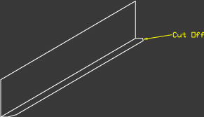
METAL CUTTING TIPS
Most metal snips leave marks on the edge of the material — some worse than others if the cutter jaws have serrations to grip the work. One way around this is to not cut directly on a finish line, but to cut about 1/16” away from the finish line. This serves two purposes — first it makes it easier to cut without worrying about cutting too deep or staying on a straight line; second, the marks made by the snips will be removed so they are not a problem. Use either a vixen file to finish the edge down to the line; or use coarse emery cloth (about 60 grit works fine) attached with staples or tacks to a straight board about 12” to 18” long. This sanding block will take the high spots down quickly and leave you with an unmarked straight edge, (no snip marks). Be careful as the edges will be sharp until you deburr.
9 - Deburring and related topics
HELPFUL DEBURRING TIPS
The Scotch-brite wheels are primarily for deburring edges of aluminum sheets. The wheels cut too much to be used on the surface of a skin (the surface conditioning product are for that use). It is a good practice to first deburr the edges of aluminum sheets & parts with a hand scraping tool. On the ends of angles and other parts it would be good to belt sand or roughly file & roughly radius all sharp corners & edges. Your wheels will last longer and wear down less quickly if you take this step before running the parts against the wheel. The Scotch-brite wheels can be dressed down when needed by carefully running a sharp steel object (needs to be supported as rigid as possible) against the edge of the wheel while the wheel is turning. Note that whatever you use (old file, chisel, etc.) will be cut down, so don’t use anything you do not wish to be dulled or cut down. Above all, be extra careful & wear eye protection when dressing wheels — it’s messy!!
DEBURRING TECHNIQUE
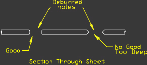
Holes can be deburred with a deburring tool or a drill bit of a larger size than the hole being deburred -BY HAND ONLY! NOT IN A DRILL! Simply put the drill bit into the hole and twist just enough(usually one rotation) to remove burr only. Don’t go too deep. See figure. A cordless screwdriverwith a drill bit installed will speed things up here, but be careful not to over do it!With the swivel deburring too from Murphy aircraft, insert tool into hole and turn once. Generally thetool only deburrs one side, so you may have to repeat it for the opposite side.
PREPARE EDGES OF ALU PARTS
All edges should be filed to remove shear or tin snip marks then have the corners ‘Chamfered’, as shown in thye next figure, with a file.

PREPARING FLANGE ENDS OF ALU PARTS
All flange ends should have corners rounded or at least be cut at 45 degrees, then filed.
PREPARING CORNERS
They should always have the largest possible radius in the corner.

10 - Bucking bars and related topics
BUCKING BAR TIPS
Bucking bars come in many shapes and sizes. Generally the heavier the bar, the better the bar works for upsetting the shop head side of the rivet. Also, the larger the working face size; the less chance you will slip off the face and damage the work or rivet. Most bucking bars have two surfaces polished to set rivets on, and the rest of the bar will be a rough cast finish. You can get extra versatility out of a bar if you belt sand and polish some of the other cast surfaces -- usually a side, edge, or opposite end. Use a belt sander first, and then a Scotchbrite wheel to finish. In a pinch, you can use any steel object as a bucking bar -- look around your shop & tool box and you will usually find a tool or part that will work as a bucking bar (does not need to be heat treated if just used for a few rivets).
Bucking bars are made in various shapes, sizes and weights. The weight of the bucking bar must be proportional to the size of the rivet. To obtain a proper upset head, a good technique to use is shown in next figure. As the gun is firing, press the bucking bar firmly against the forming rivet shank and roll the bar slightly. This rolling action will aid in the formation of a barrel-shaped bucktail. If the bucking bar is too light for the size of rivet and gun, the metal will bend toward the bucktail. If the bucking bar is not held firmly against the rivet shank, the metal will bend away from the gun.
11 - Hand seamer and related topics
WHAT IS A HAND SEAMER ?
Hand seamers are used like a hand held bending brake. You can bend small flanges, straighten flanges, bend tabs in different directions, etc. with a hand seamer. For aircraft work make sure you get a hand seamer that has a radius on the edge of the jaw so you don’t bend too sharp of a radius and scratch or mark the inside of the bend radius -- (both are bad practices for aircraft as fatigue cracks can result). Note that most welding & duct-work seamer pliers have too sharp of an edge for aircraft work and their jaws may be too thin to grind or modify with a radius for aircraft work.
12 - Dimple dies and related topics
WHAT ARE "SPRING BACK DIMPLE DIES"?
Spring back dimple dies are dies with a special angle machined on the faces of both dies. The male dimple die has a concave angle (negative taper) of about 1 degree on its surface, and the female dimple die has a convex angle (positive taper) of about 2 degrees to its face. This angle causes the material being formed to bend slightly upward (over-bend) during forming as the dies are pressed together and bottom out. After dimpling the surface "springs back" to a flat surface to give a better and smoother finish. This slight amount of taper on the dies is not much but it makes a big difference in the surface finish after riveting. (The skill & experience of the riveter / bucker make an even bigger difference, also).
Note that due to the (negative) taper of the male die, you will experience a faint / slight marking on the top surface of the part being dimpled, about the size of the diameter of the die. This marking is not deep enough to cause any problems. This slight marking of the surface can be removed with a Scotchbrite handpad in the same manner as you would prepare the surface for painting.
Dimpling
Thin skins are never machine countersunk, because the cutter will go completely through the thin skin into the second skin and reduce the bearing strength around the countersunk rivet head. There is an alternative process call dimpling, which solves this problem. Dimpling can be done in two ways, cold dimpling or hot dimpling. Cold dimpling of sheet metal skins is done on material less than .040 of an inch thick if countersunk rivets are required. The benefit of cold dimpling is that it produces stronger shearing and bearing strengths in the joint than would a driven universal head rivet of the same size.
Dimpling bars or sets can be made in the shop by cutting steel stock to the same size as the rivet to be used, and then setting a microstop countersink to cut about .015 of an inch deeper than the rivet head. To use the dimpling bar, drill a hole into the sheet metal just as you would for a universal head rivet, place the dimpling bar under the rivet hole and insert a countersink rivet. Using a rivet gun with a mushroom head set or a ball peen hammer, tap the rivet head into the dimpled well. Because dimpling does not produce the flushness of a machine countersunk rivet, be careful not to hit the area around the head too hard, or the metal surrounding the rivet will stretch, creating a problem which could be difficult to remedy. Metal that becomes stretched must be removed and replaced either by a patch or by changing a complete skin panel.
13 - Metal surface preparation
As a protective measure against corrosion, mating metal surfaces should be fully deburred, cleaned, then coated liberally with epoxy chromate primer. This provides a seal between the surfaces to prevent corrosion and moisture buildup. It is a good practice to coat the end of the rivet on the inside surface after installation. As an optional measure, the rivets can be dipped in chromate prior to installation. This provides protection inside the hole and seals out moisture. If the airframe is not to be painted be careful to avoid excess chromate on the exterior.The epoxy primer is to be pre-mixed in accordance with the manufacturers directions as displayed on the containers. It is advisable to mix only the amount you need in a small container each time you work, however, larger amounts can be mixed and reused in a sealable container.
14 - Rivets
The standard rivet used in the aircraft is the avex rivet. Many people mistakenly refer to them as poprivets. “Pop” is a brand name and the correct terminology is blind rivet which simply means it can be used from one side only. There are considerable differences between the avex rivet and the more common poprivet. Never substitute a pop type rivet for the avex rivets. Rivets can have various lengths. Sometimes countersunk or domed head avexrivets are used. Stainless steel rivets are used sometimes, normally in high shear application. Check carefully with the instructions on where to use the different types, lengths and heads. You can also find a number of large head all aluminum rivets. These rivets are non-structural and are mostly used in installing the windows.
- Always check that you are using the proper grip length rivet for the job you are doing. I.E.: 1/8: X 1/8” rivet refers to ‘Diameter’ and ‘Grip’ length will secure only up to 1/8” of material thickness, just as a 1/4” grip length rivet will secure only up to 1/4” of material.
- Make sue the rivet is all the way into the hole and that the parts being riveted have not pulled away from each other or separated.
- Keep rivet gun square to the work when pulling rivets.
Edge distance is simply the distance from the center of the rivet or bolt to the edge of the skin or fitting. The proper edge distance is required to ensure that the rivets or bolts are not ripped from the skin/fitting because of inadequate shear strength.
The rule of thumb is that edge distance from center line hole to edge of material should always equal twice the rivet/bolt diameter. Normally 1/16” is added in case you have to drill to the next size or too much material is trimmed off. To go any greater dimension than this does not increase the strength, it just adds extra weight and is unsightly. A circle template will assist you and is very cheap and easily purchased. Most office or school supply stores carry them.
Always make sure that you have adequate edge distance on your parts. Rule of thumb for edge distance is
Rivet/bolt diameter X2 or....
1/8” rivet X2 = 1/4” edge distance
3/16” bolt X2 = 3/8” edge distance
Never have less than 1 1/2 ties edge distance. Avoid more than 2 1/2 times edge distance.
Aircraft Solid-Shank Rivets
Only the solid-shank rivet increases, when it is properly installed, in size and strength. A steel bolt, for example, will actually decrease in diameter when it is installed and torqued. Some manufacturers of special fasteners attempt to duplicate the natural action of solid-shank rivets by putting expanding sections on the fasteners’ pulling stems. Most of these special fasteners only approximate the natural shank expansion of a driven solid-shank rivet. Since pure aluminum weights one-third as much as steel, aluminum alloy solid-shank rivets are lighter than many other fasteners. Their lightness is an advantage, but it limits their usefulness: Solid-shank rivets greater than 1/2- inch in diameter are not used. However, the allowable range, 3/32 to 1/2- inch indiameter, is broad enough for the needs of most typical aircraft construction and repairs.
Riveting Solid Shank
Riveting is sometimes referred to as a “mushrooming” process. When the rivet is being driven, certain physical changes take place. The rivet diameter cross-sectional area increases, the hardness of the rivet increases due to coldworking, the manufactured head expands, and the shank expands to the size of the hole. The result of this mushrooming process is that the rivet is coldworked, changing its temper designation from T4 to T3. There are tree steps involved in planning and executing a solid-shank rivet joint for structural repair: Layout, installation, and inspection.
|
Rivet|
Diameter
|
Drill
Size
|
Cleco
Color
|
Bucking Bar
Weight
|
Edge
Distance
|
Rivet
Pitch
|
|
3/32
|
40
|
Silver
|
2-3.0 lbs
|
6/32
|
9/32
|
|
1/8
|
30
|
Copper
|
3-4.0 lbs
|
1/4
|
3/8
|
|
5/32
|
21
|
Black
|
3-4.5 lbs
|
10/32
|
15/32
|
|
3/16
|
11
|
Gold
|
4-5.0 lbs
|
6/16
|
9/16
|
In the chart above shows the rivet sizes, drill sizes, Cleco colors, bucking bar weights, minimum edge distances, and minimum rivet pitches for layout and installation of the commonly used solid-shank rivets. Rivet spacing is important when laying out rivets to obtain a joint which is structurally sound and aesthetically balanced. The layout of rivets may be in rows abreast or transverse. One of the advantages of placing rivets in transverse row is that it reduces rivet failure along the metal’s grain structure. Rivets laid out in rows abreast have a greater tendency to fail along the grain. Rivet pitch is the distance between one rivet or row of rivets and the next rived or row of rivets. (Some handbooks refer to rivet pitch as gage) Minimum rivet pitch is 3D, or 3 diameters, of the rivet being driven. (The diameter of a rivet is expressed as D and the length as L) Average rivet pitch is 6 to 8 diameters. Maximum rivet pitch is 24 times the thickness of the top sheet of metal. Minimum transverserivet pitch is 2.5 diameters of the rivet being driven. See Figure:
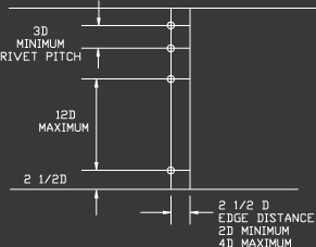
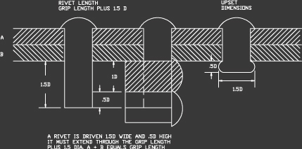
Edge distance is the distance from the edge of the metal to the center of the first rivet or row of rivets. On aircraft, the minimum edge distance is 2D and the maximum is 4D. If an edge distance is larger than 4D, the edges may curl upwards and not lie flat and binding. When aircraft rivets are installed using less that 2D edge distance, the bearing edge strength of the metal will weaken. To select the correct drill, and to drill the holes to the proper size. All rivet holes must be center punched in order to prevent the drill from walking over the surface of the metal and defacing it. The indentation made by a center punch must be hard enough to catch the point of the drill, yet light enough to prevent denting the surrounding mental. Proper drill selection depends upon the size of the rivet being used. The hole for a solid-shank rivet is drilled approximately .002 to .004 of an inch larger than the nominal rivet diameter. A rivet that is driven into a properly prepared hole needs to be sized according to diameter and length so that a correct size bucktail can be formed. The next figure shows the width and height of a normally driven bucktail.
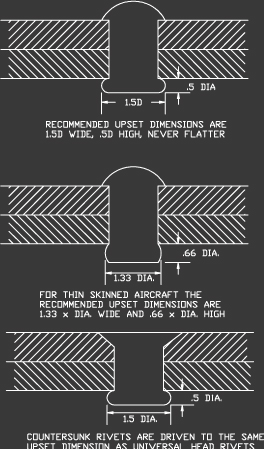
The use of thin skins on many light aircraft requires that the upset rivet head be .66 times the diameter of the rivet high, and 1.33 inches times the diameter of the rivet wide. To determine the rivet length for a particular job, the thickness of all the metal parts must be known. All the individual thickness of the metal are referred to as the grip length. The grip length plus 1.5D is the proper length of the rivet.
The hand tool used to drive a rivet is called a pneumatic rivet gun or rivet hammer. Rivet guns are normally powered by compressed air and are classified as light-, medium-, or heavy-hitting. A light-hitting gun is used to install 3/32 and 1/8 inch diameter rivets. Medium-hitting guns are used to install 5/32 and 3/16 inch diameter rivets. Heavy-hitting guns are used to install larger diameter rivets and some special fasteners. There are two types of gun sets, one for universal head rivets and one for countersunk. The universal gunset is sized to fit the various shapes of manufactured heads on the rivet’s driven end. The opposite end of the universal gun set fits into the rivet gun barrel and is held in place by a beehive retainer spring. The countersunk gun set fits all sizes of flush head rivets. The countersunk rivet cannot use the beehive retainer ring. The countersunk rivet set uses a specially designed retainer spring.
Rivet Codes and Identification
The manufacturing of all solid-shank rivets is governed by Federal Specifications and Standards QQ-A-430. Solid-shank rivets are identified and cataloged by head shape, alloy contend, shank diameter, and shank length. See figure:

Two shorthand methods of coding are used to identify all aircraft rivets. An example is AN470AD4-5, or MS20470AD4-5. AN means Air Force-Navy and MS20 means Military Standards 20; 470 designates a universal style rivet head; AD refers to the alloy 2117T4: the hyphenated numbers designate the rivet diameter in thirty-seconds of an inch and the length in sixteenths of an inch. Thus, in the example, 4 means 4/32nds-inch diameter, and 5 means 5/16ths-inch length.
Although the AN and MS20 methods of cataloging rivets are similar, it is important to consistently use one of the two methods when ordering or identifying rivets. The rivet code is also used in blueprints, drawings, and technical manuals.
Rivet Head Styles
Four styles of rivet heads are used to construct an aircraft: round, flat, universal, and countersunk. The latter two are the most commonly used in the aircraft industry. The next figure is a cross-sectional view of the universal and countersunk head rivets, showing their diameters and lengths.
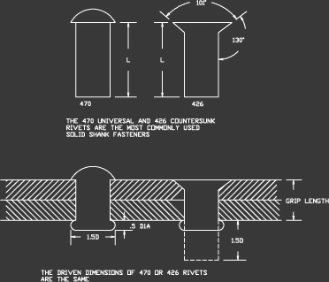
Universal head rivets
Universal head rivets, also called protruding head rivets, are used internally in structural areas and on the skin surfaces of low to medium speed aircraft. A universal head rivet can with stand a much stronger bearing load than a countersunk rivet because the head is installed flat and binding on the surface of the riveted metal while the countersunk rivet is installed into a machine-tapered will. The universal head rivet is a combination of several older head styles. When rivets were first used,various rivet head styles were available. Round head (AN430) rivets were used internally on high strength structural areas. The flat head (AN442) rivet was used in tight areas where the round head could not be installed. Some modern jet aircraft still use round and flat head rivets in structural areas. Aircraft built prior to World War II were low speed aircraft, so a smooth aerodynamic air flow over the wing was not a major concern. As the speed of the aircraft increased, the need for smaller protruding head rivets accounted for the development of a modified brazier head (456), which causes less drag than larger protruding head rivets. Today, brazier head rivet styles are likely to be found only on aircraft built before 1955. Because the rivet sets used to drive rivets other than universals are difficult to obtain today, the older styles can be replaced by universal head rivets. Advisory Circular 43.14-1 explains the procedure.
Countersunk Rivets
As aircraft speeds increased, the need for smooth airfoils led to the development of the countersunk rivet. After experimenting with head angles of 78 degrees, 90 degrees and on high-speed jet fighters, 110 degrees, the aircraftindustry adopted a 100 degrees standard. All of these experiments were attempts to increase the bearing strength of the rivet head around the skin. The countersunk rivet has to be installed in a depression in such a way as to be flush with the surface of the skins it is holding together. The depression in the skin is called a nest or a well. The well can be made using a freehand or microstop countersink cutter. Whenever the metal is cut to form a well or nest, the area around the rivet head is weakened. To compensate for this loss of strength, aircraft manufactures must install a greater number of rivets in order to increase bearing and shearing strengths. Next figure shows how countersunk rivets are installed, by either machine or dimple methods
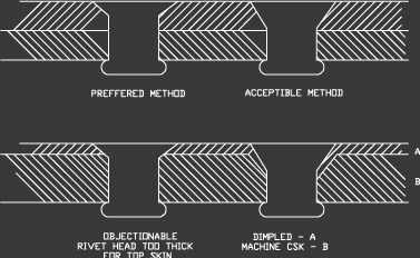
To remedy the loss in bearing strength caused by machine countersinking, the NACA (National Advisory Commission for Aeronautics) developed a method of countersinking that has been adopted by aircraft manufacturing companies. Two different angles may be cut into the top skin, 60 degrees or 82 degrees . Military aircraft were the first to use the 60 degrees well, on some of the older jet fighters. The 82 degrees well is used when installing sing slugs on the Boeing747. On some aircraft, a universal is installed from the inside of the wing and driven into an 82 degrees well. Installing rivets using either the 60 degrees or 82 degrees NACA countersink method makes them as strong as universal head rivets. When cold worked, the bucktail formed in the 60 degrees or 82 degrees angle well is stronger than the conventional countersink riveting method because the driven head is packed into its well, creating a much stronger head than the regular countersunk rivet can produce.
Inspection of a Rivet Joint
There are three places to check when inspecting a rivet joint: The MFG-head, the shop head, and the skin around the rivet heads. Any damage to either of the two rivet heads is not critical because rivets can be drilled out and replaced. Note: Never oversize the hole when drilling out a damaged rivet!
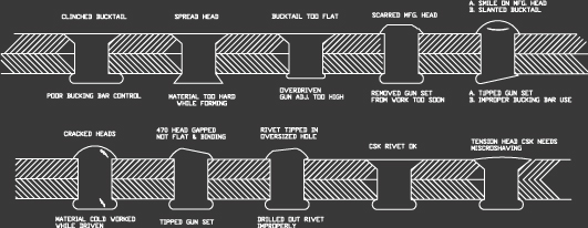
If skin damage is extensive, a new skin panel must be installed. The procedures for removing rivets depends upon the situation. If, for example, an aircraft has extensive damage to a wing leading edge or a section of the spar, the mechanic will remove the damaged metal as well as some of the parts that are still useable. In removing rivets from reusable aircraft parts, it is essential that the rivet holes not be oversized. The correct way to remove the rivets is to file a flat spot on all protruding head rivets except the 2117 rivets, to center punch each MFG. head, to back up each rivet with a bucking bar, to select a drill ONE SIZE SMALLER THAN THE RIVET BEING REMOVED, to drill only the depth of the MFG-head, touse a pin punch which is the same size as the drill, to snap off the drilled MFG-heads and to back up each remaining stem by tapping out the shank without stretching the metal. A different procedure is followed in removing the occasional rivet badly driven during re-assembly. Such rivets should be removed by the same size drill as the rivets being installed. Drill the depth of the MFG-head only; then lightly tap off the MFG-head and gently knock out the remaining shank. Next figure illustrates an assortment of faulty rivets which must be removed and replaced. The most troublesome rivet fault is a clinched rivet, which results from improper bucking action. The rivet forms to one side, which can lead to a corrosive condition at a later date. Rivets that crack do so because they became too hard while the bucktail was forming. This is a result of hitting the rivet too lightly or allowing an icebox rivet to recover its age hardening by keeping it out of the freezer too long before driving.
15 - Bolts
Throughout the building process there will be instances where bolts are used to fasten parts or materials together. In some instances It may be for the builder to determine the correct length of the bolt to be used. The “Rule of Thumb” for determining bolt length is that the bolt must be long enough to pass through the parts or material being fastened together so that:
- The threaded part of the bolt is never in shear (no threads are allowed inside hole).
- No more than three and no less than one thread must be showing when the nut isattached and tightened to the correct torque value.
- At least on flat washer must be used under the nut and no more than three are allowed.
More precise determinations of Grip Length are found in a number of books including the Standard AircraftWorker’s Manual.
The following information is provided for reference when using AN grade hardware. Most of the time torque values are done to feel. But this table does provide a good outline. Occasionally bolts, other than a standard bolt will be called out for use in the manual. Please ensure that these bolts are used where called out. They were selected as they provide the strength for the connection where a standard bolt can not provide.
Standard Torque Table (Inch Pounds) *
FINE THREAD SERIES
| Bolt Size |
Standard Nuts
(MS20365, AN310, AN315) |
Shear Nuts
(MS20364, AN320, AN316, AN23-31) |
|
10-32
|
20-25
|
12-15
|
|
1/4-28
|
50-70
|
30-40
|
|
5/16-24
|
100-140
|
60-85
|
|
3/8-24
|
160-190
|
95-110
|
|
7/16-20
|
450-500
|
270-300
|
|
1/2-20
|
480-690
|
290-410
|
|
9/16-18
|
800-1000
|
480-600
|
|
5/8-18
|
1100-1300
|
660-740
|
COARSE THREAD SERIES
| Bolt Size |
Standard Nuts
(MS20365, AN310, AN315) |
Shear Nuts
(MS20364, AN320, AN316, AN23-31) |
| 8-32 |
12-15
|
7-9
|
| 10-24 |
20-25
|
12-15
|
| 1/4-20 |
40-50
|
25-30
|
| 5/16-18 |
80-90
|
48-55
|
| 3/8-16 |
160-185
|
95-110
|
| 7/16-14 |
235-255
|
140-155
|
| 1/2-13 |
400-480
|
240-290
|
| 9/16-12 |
500-700
|
300-420
|
| 5/8-11 |
700-900
|
420-540
|
* The above calculations were obtained from the Standard Aircraft Handbook.
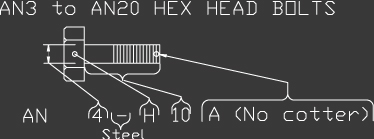
AN bolts may be obtained in the following materials. The coding symbols shown follow the basic dash number and identify the material required in the callout. The figure shows how the material of the bolt may be distinguished by bolt head markings.
| ( - ) |
= Steel, cadmium plated |
| C |
= Corrosion resisting steel |
| DD |
=Aluminum alloy |
Example: AN4 - H10A
| AN |
- Army Navy Standard |
| 4 |
- Diameter in 1/16 inch increments or 1/4 inch diameter |
| ( - ) |
- Steel, cadmium plated |
| H |
- Bolt with drilled head and shank required; leave off if plain head required |
| 10 |
- Refer to table 1 for bolt length and bolt thread corresponding to “10” |
| A |
- The adding of the letter A indicates that the cotter pin hole is not required |
Note: To determine grip length, deduct the figure indicated below from the lengths shown
in table 1.
| AN3 - 13-32 |
AN8 - 25-32 |
AN14 - 1-1/4 |
| AN4 - 15/32 |
AN9 - 29-32 |
AN16 - 1-3/8 |
| AN5 - 17/32 |
AN10 - 61/64 |
AN18 - 1-1/2 |
| AN6 - 41/64 |
AN12 - 1-3/32 |
AN20 - 1-11/16 |
| AN7 - 21/32 |
|
|
AN3-AN20 Hex Head Bolt Length
Table 1: Bolts
| Dash Number |
AN3 |
AN4 |
AN5 |
AN6 |
AN7 |
AN8 |
AN9 |
AN10 |
| 10-32 |
1/4-28 |
5/16-24 |
3/8-24 |
7/16-20 |
1/2-20 |
9/16/18 |
5/8-18 |
| 3 |
15/32 |
15/32 |
|
|
|
|
|
|
| 4 |
17/32 |
17/32 |
19/32 |
|
|
|
|
|
| 5 |
21/32 |
21/32 |
23/32 |
45/64 |
23/32 |
|
|
|
| 6 |
25/32 |
25/32 |
27/32 |
53/64 |
27/32 |
27/32 |
31/32 |
|
| 7 |
29/32 |
29/32 |
31/32 |
61/64 |
31/32 |
31/32 |
1-1/32 |
1-1/64 |
| 10 |
1-1/32 |
1-1/32 |
1-3/32 |
1-5/64 |
1-3/32 |
1-3/32 |
1-5/32 |
1-9/64 |
| 11 |
1-5/32 |
1-5/32 |
1-7/32 |
1-13/64 |
1-7/32 |
1-7/32 |
1-9/32 |
1-17/64 |
| 12 |
1-9/32 |
1-9/32 |
1-11/32 |
1-21/64 |
1-11/32 |
1-11/32 |
1-13/32 |
1-25/64 |
| 13 |
1-13/32 |
1-13/32 |
1-15/32 |
1-29/64 |
1-15/32 |
1-15/32 |
1-17/32 |
1-33/64 |
| 14 |
1-17/32 |
1-17/32 |
1-19/32 |
1-37/64 |
1-19/32 |
1-19/32 |
1-21/32 |
1-41/64 |
| 15 |
1-21/32 |
1-21/32 |
1-23/32 |
1-45/64 |
1-23/32 |
1-23/32 |
1-25/32 |
1-49/64 |
| 16 |
1-25/32 |
1-25/32 |
1-27/32 |
1-53/64 |
1-27/32 |
1-27/32 |
1-29/32 |
1-57/64 |
| 17 |
1-29/32 |
1-29/32 |
1-31/32 |
1-61/64 |
1-31/32 |
1-31/32 |
2-1/32 |
2-1/64 |
| 20 |
2-1/32 |
2-1/32 |
2/3-32 |
2-5/64 |
2-332 |
2-3/32 |
2-5/32 |
2-9/64 |
Table 2 Screws
Recommended Hole Sizes for Self-tapping Sheet Metal Screws
| Metal |
|
Clearance Drill for Sheet Metal Screws |
| Thickness |
Material. |
#2
|
#4
|
#6
|
#7
|
#8
|
#10
|
#12
|
#14
|
| 0.015 |
Steel |
52
|
44
|
37
|
|
|
|
|
|
|
Alum. |
|
|
|
|
|
|
|
|
| 0.018 |
Steel |
52
|
44
|
37
|
33
|
|
|
|
|
|
Alum. |
|
|
|
|
|
|
|
|
| 0.024 |
Steel |
51
|
43
|
36
|
32
|
27
|
19
|
|
|
|
Alum. |
52
|
|
|
|
|
|
|
|
| 0.03 |
Steel |
50
|
42
|
36
|
32
|
31
|
27
|
19
|
13
|
|
Alum. |
52
|
44
|
37
|
33
|
32
|
|
|
|
| 0.036 |
Steel |
49
|
42
|
35
|
32
|
31
|
26
|
19
|
13
|
|
Alum. |
52
|
44
|
37
|
33
|
31
|
27
|
|
|
| 0.048 |
Steel |
49
|
41
|
34
|
31
|
30
|
24
|
18
|
11
|
|
Alum. |
51
|
44
|
37
|
32
|
30
|
27
|
20
|
|
| 0.06 |
Steel |
48
|
39
|
32
|
30
|
29
|
24
|
16
|
8
|
|
Alum. |
50
|
43
|
36
|
31
|
29
|
27
|
19
|
8
|
| 0.075 |
Steel |
|
38
|
31
|
29
|
28
|
22
|
14
|
6
|
|
Alum. |
|
43
|
35
|
30
|
28
|
26
|
17
|
7
|
| 0.105 |
Steel |
|
|
30
|
28
|
25
|
20
|
13
|
4
|
|
Alum. |
|
42
|
34
|
29
|
26
|
26
|
15
|
6
|
| 0.125 |
Steel |
|
|
|
|
25
|
18
|
9
|
1
|
|
Alum. |
|
|
31
|
29
|
26
|
23
|
14
|
4
|
| 0.135 |
Steel |
|
|
|
|
24
|
18
|
9
|
1
|
|
Alum. |
|
|
31
|
29
|
25
|
23
|
14
|
4
|
| 0.164 |
Steel |
|
|
|
|
|
17
|
7
|
15/64
|
|
Alum. |
|
|
31
|
29
|
24
|
21
|
12
|
3
|
| 0.187 |
Steel |
|
|
|
|
|
17
|
7
|
15/64
|
|
Alum. |
|
|
31
|
29
|
24
|
21
|
12
|
3
|
16 - Nuts
AN310 CASTELLATED NUT

The AN310 Castle Nut is designed to be used in conjunction with a cotter pin for safetying. The nut may be used in tension and on assemblies that turn on the bolt or vice versa. This nut is used primarily with the AN3 to AN20 series bolt.
Example Callout:
AN310D4 An AN310 aluminum nut (D) for use on a 1/4 in (4) bolt. Thread from table - 1/4-28NF-3.
AN315 PLAIN NUT

The AN315 Plain Nut may be safetied through the use of a shakeproof or lock washer - may be used inconjunction with the AN3 to AN16 series bolt. The nut may be had in right (R) or left (L) hand thread (see example callout).
AN316 CHECK NUT

This nut is used as a check nut to eliminate travel of other nuts or parts on the threads of a bolt or rod. This nut must not be used in tension or shear. The AN316 nut may be had in either right (R) or left (L) hand thread (see callout).
UNF-3 THREAD SIZE
|
6-40
|
8-36
|
10-32
|
1/4-28
|
5/16-24
|
3/8-24
|
7/16-20
|
1/2-20
|
9/16-18
|
5/8-18
|
3/4-16
|
7/8-14
|
1-14
|
1-1/8-12
|
1-1/4-12
|
|
|
|
-3
|
-4
|
-5
|
-6
|
-7
|
-8
|
-9
|
-10
|
-12
|
-14
|
-16
|
-18
|
-20
|
|
|
|
-3
|
-4
|
-5
|
-6
|
-7
|
-8
|
-9
|
-10
|
-12
|
-14
|
-16
|
-18
|
-20
|
|
|
|
|
-4
|
-5
|
|
-7
|
-8
|
-9
|
-10
|
-12
|
-14
|
|
-18
|
-20
|
|
-1
|
-2
|
-3
|
-4
|
-5
|
-6
|
-7
|
-8
|
-9
|
-10
|
-12
|
-14
|
-16
|
-18
|
-20
|
AN365 SELF-LOCKING FIBRENUT

The Fibrenut is used extensively throughout the aircraft. Because of the locking ability of the fibre in the nut cotterpins or lock washers are not needed. Do not use the same fibrenut over and over as the nylon wears with each tightening and does not give the same locking strength. If you come to a step that calls for repeated nut use on the same bolt use a plain nut until the final install
17 - Washers

The AN960 plain washer is furnished in the following materials: Steel (Cadmium plated), Aluminum alloy(D), Brass (B), and corrosion resistant Steel (C). The code letter (none for steel) follows the basic number. The inside diameter is indicated by the last dash number which is expressed in screw sizes as #6, #8 and #10, or; AN960-6, AN960-8, AN960-10. Washers requiring an I.D. or 3/8, 7/16 or 1/2 inch are called out as AN960-616, AN960-716, and AN960-816. The washer is made in a regular and light (L) series in all metals indicated except brass. If the washer is of the light (L) series, the “L” will follow the dash number .Add the letter “P” before the dash number to obtain aluminum washers that have been anodized.
The AN-970 washer provides a greater bearing area than the plain type, and is used to prevent local crushing of
the surface.
18 - Plastic coating over the parts
The plastic film on the aluminum should be left on for as long as possible during the assembly of your aircraft. This helps to prevent the aluminum from being scratched.
19 - Marking parts/Lay-outs
Use a ‘fine tip’ felt pen for accuracy (some felt pens will not write on aluminum). It will show up well and does not wipe off easily. After layouts are no longer needed, clean off felt pen marks with solvent (M.E.K. works well) before final assembly as some inks may be corrosive if left on.
20 - Fiberglass
Towards the end of the project, you will be constructing fiberglass parts for your AIRCRAFT. Each kit contains enough fiberglass cloth, resin and catalyst to complete this job. This is very easy process and one should have no trouble completing these jobs.
The following list has some recommendations about using fiberglass.
- Keep the weave of the cloth straight and mark your cuts with a black felt pen. Cut the cloth withsharp scissors.
- If the fiberglass lays smoothly while dry, it will easily conform to the mold when wetted out with resin
- Keep the fiberglass cloth clean. If possible, keep it in an area away from where you will be using the resin. Oil, dirt or solvents will deteriorate the cloth and prevent the resin from improperly bonding to the cloth.
- It is much easier to handle fiberglass cloth if you spread it over a smooth slick surface. Keep the loose ends of the fiberglass trimmed if possible
- Keep all the necessary tools at hand. Ensure you have good light, work in a well ventilated and temperature controlled area. Keep the room temperature around 75 to 85 degree Fahrenheit. Always abide by the instructions and warning labels provided on the resin containers.
- Allow yourself plenty of time to work with the fiberglass and resin. If more information is required about the use of fiberglass or lay-up procedures, an excellent reference book is Sportplane Construction Techniques by Tony Bingelis. This book can be purchased at any EAA Bookstore or EAA Chapter.