| Wing Kit |
1. Accessories I already ordered because they are related to the wing section.
It's nice to be prepared... Almost all the accessories necessary to finish the wings are already present in the shelf. Let me be clear... almost... I'm still studying which pitot tube I will order, I have to inform myself which stall warning (absolutely neccessary for the Belgian Authorities in an RV7) I have to install, and, last but not least, which autopilot I will install. These are the missing accessories for the moment. At the time I have made my decisions, I will put more information in this wing-related chapter. But, in the meantime, hereunder the several items I choosed to build into the wingsection...
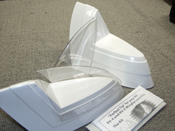
A. The wing tip lenses
The wingtip lenses Van's offers are very nice. They give a final touch on the wing and they are ideal to protect the anti collision and stobe lights. Ideal should be to put led wing tip lights (red and green) in these beauties. But that is something I have to check with the authorities first. I don't know if this is already allowed for the Belgian Aviation Authorities. Nevertheless, if I should receive a positive answer on this question, I will still decide to change my traditional lights into this new technology... In the meantime I ordered the Whelen lights (kit 6 in the Van's catalogue) to put into my wing tip lenses...
(Van's reference: Airtech Wingtip Lens kit for usage on the RV7 wingkit, Catalogue reference LN AT TIP LITE and price: 179 $).
B. System 6 light kit Whelen
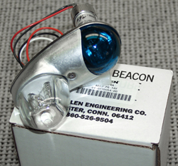
The wingtip lights (combination Anticollision and strobe) as I ordered them now. Possibly this will be changed into led lights if allowed by the Authorities...)
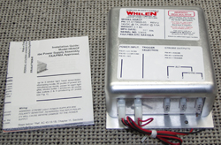
This is the complete System 6 set of Whelen. All included, the wingtip lights, the taillight and the strobe. Until I have a confirmation of the Belgian Aviation Autorities that I have the permission to use the LED-tiplights, this is my choice. I will keep you informed about this. The reason why I prefer the LED is the lower power consumption of LED and, of course related on this, the smaller wires I can use. And... I like new technologies.
(Van's reference: System 6 lights (position lights, wingtip strobes and combination tail light/strobe, Catalogue reference LN SYS6 and price: 780 $).
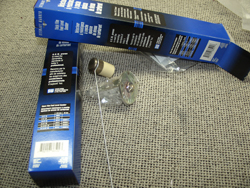
C. Landing and Taxilights from Duckworks
I choosed to build two Duckworks landing and taxilight sets in the leading edge of the wing. There is a more expensive option in this system if you choose for the HID lights. The advantage of HID (High Intensity Discharge) light system did not convince me to choose for a 2 x 335 $ higher price. I choosed for the 2 x 115$ Halogen Round Lighting Bulb system because in a later phase, if not sufficient, I can upgrade it to the HID system...
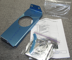
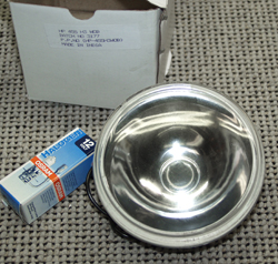
(Van's reference: Two sets Round 100 W Landing/Taxilights for RV7 from Duckworks, Catalogue reference: 2 x RLL DW-02 RV7 and price: 230 $ ).
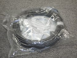
D. Nylon Wiring Conduit
Not included in the kit, but in my opinion, essential for wire runs in the wings and the fuselage, is this option that Van's offers. The reference brings you to the information page of this 50' roll of nylon corrugated tube in the Van's catalogue. This 12.20$ tube is really a "must have" option when you start the wing building...
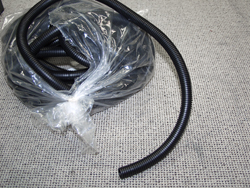
(Van's reference: 50' roll of nylon corrugated tube, Catalogue reference: DUCT NT5/8-50 and price: 12.20 $).
E. Inverted Fuel Pick-up
Unless you build an RV-7 to fly only straight forward and never upside down, you need this option. This Flop-tube is necessary to pick-up fuel when you possibly will ever fly inverted. Now it is possible to put this low-cost option into your fuel tanks, later this would be rather impossible... So, why not? I put one of these in each tank...
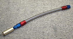
(Van's reference: Wing tank flop tube, Catalogue reference: IF-4/6 and price: 2 x 35 $).
F. Fuel Senders
Well, until now I choosed for the Float Type sending units. These are resistive and operate between approximately 20-240 ohms. The reason why I choosed these is because the Dynon EFIS (for which I choosed until now) only work with this type of sending units. But, if necessary, I can change it or build-in another type also...
(Van's reference: IE F-385 Sending Units and Gaskets, Catalogue reference: IF-385B and C and price: 2 x 27 $).
G. Fuel Tank Test Kit
This choice talks for itself I think...
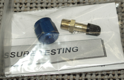
(Van's reference: Fuel Tank Test Kit, Catalogue reference: Fuel Tank Test Kit and price: 5 $).
H. ProSeal
Sealing the home-built fuel tanks...
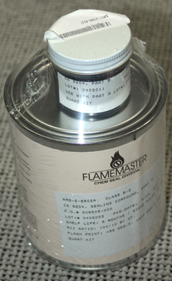
(Van's reference: Proseal sealing kit, Catalogue reference: Proseal MC-236-B2 and price: 39.3 $).
I. Deluxe Fuel Cap
Not yet ordered but in the meantime decided to put in my wings. They are not really cheap, but, in comparison with the standard delivered fuelcaps tese are really beauties...
(Van's reference: Deluxe Fuel Caps, Catalogue reference: Locking Cap with Flange and price: 2 x 90 $)
2. Tracking information and valuable shipping info.
Interesting for colleagues builders is the information hereunder. You can see the dimensions, weights and times to ship this wing section to its destination. And, transit and handling times in between...
These were my shipment histories. The shipment came by Bax Global...
![]()
TRACKING INFORMATION
| Tracking Number: | 47033766 |
| Filtered By: | Tracking Number 47033766 |
SHIPMENT INFORMATION
| Status: | In Transit From |
| Signature: | |
| Service Level: | Prime |
| Shipped Date: | 14-Jan-2005 |
| Origin: | Aurora, OR, US |
| Destination: | Arendonk, B-2370, , BE |
PACKAGE INFORMATION
| Pieces: | 2 |
| Actual Weight: | 179.0 kgs |
| Volume Weight: | 130.0 kgs |
| Dimensions: |
DIMENSIONS
| PIECES | LENGTH | WIDTH | HEIGHT |
| 1 | 186 | 10 | 9 |
| 1 | 96 | 32 | 10 |
REFERENCES
| REFERENCE DESCRIPTION | REFERENCE NUMBER |
| SHIPPER'S REFERENCE | 71881 |
| CUSTOMER REFERENCE NUMBER | N/A |
| XTN NUMBER FOR AES-CUSTOMS | 04703376601239745 |
SHIPMENT HISTORY
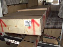
Our Van was just long enough to transport the shipment. Two big boxes... The second
part of the project can start. Read more hereunder in the building log...
| DATE | TIME | PIECES | ACTIVITY | LOCATION | REMARKS |
| 26-Jan-2005 | 11:00 | 2 | Joeri, my oldest son drove to Bax Global in Melsbroek Brucargo, to pick-up the wing shipment | Brussels, BE | |
| 25-Jan-2005 | 10:00 | 2 | Called BAX Global in Brussels | Brussels, BE | The 2 pieces are about to be declared by the Belgian authorities and can be picked-up tomorrow... |
| 25-Jan-2005 | 10:50 | 2 | Consignee Notified | Brussels, BE | |
| 24-Jan-2005 | 11:00 | 2 | Consignee Notified | Brussels, BE | |
| 20-Jan-2005 | 13:20 | 2 | Consignee Notified | Brussels, BE | |
| 20-Jan-2005 | 13:53 | 2 | Arrived | Brussels, BE | |
| 18-Jan-2005 | 11:46 | 2 | In Transit From | Chicago O'Hare, Illinois, US | SQ 83731163 FLT SQ7975/19 ETA BRU 0700/20 |
| 17-Jan-2005 | 16:00 | 1 | Scanned | Atlanta, Georgia, US | |
| 17-Jan-2005 | 16:00 | 2 | Arrived | Atlanta, Georgia, US | |
| 16-Jan-2005 | 21:00 | 1 | Departed | Chicago/O'Hare Airport, Illinois, US | |
| 16-Jan-2005 | 21:00 | 1 | Departed | Chicago/O'Hare Airport, Illinois, US | |
| 16-Jan-2005 | 21:00 | 1 | Departed | Chicago/O'Hare Airport, Illinois, US | |
| 16-Jan-2005 | 17:03 | 1 | Scanned | Chicago/O'Hare Airport, Illinois, US | |
| 16-Jan-2005 | 17:03 | 1 | Scanned | Chicago/O'Hare Airport, Illinois, US | |
| 16-Jan-2005 | 17:03 | 1 | Scanned | Chicago/O'Hare Airport, Illinois, US | |
| 16-Jan-2005 | 17:03 | 2 | Arrived | Chicago/O'Hare Airport, Illinois, US | |
| 14-Jan-2005 | 20:00 | 1 | Departed | Portland, Oregon, US | |
| 14-Jan-2005 | 20:00 | 1 | Departed | Portland, Oregon, US | |
| 14-Jan-2005 | 18:48 | 1 | Scanned | Portland, Oregon, US | |
| 14-Jan-2005 | 18:05 | 1 | Scanned | Portland, Oregon, US | |
| 14-Jan-2005 | 17:52 | 1 | Scanned | Portland, Oregon, US | |
| 14-Jan-2005 | 16:17 | 2 | Shipment Labeled | Portland, Oregon, US | |
| 14-Jan-2005 | 16:37 | 2 | Received | Portland, Oregon, US |
3. Wing Building Log.
| Saturday, January the 29th 2005 | Inventory of the received Wing kit |
| I received the two boxes with the complete wing section parts. Elvira and I started to make the inventory of the shipment today... | |
| After we took the 179 kg boxes out of the Van, I started immediately to open these very well packed crates... | |
| Moment Surpreme... First look inside. I can imagine the feeling archeologists have at the moment they open a sarcophage of an ancient mummie. This, for sure, gave me probably a comparable thrill... |
|
| Again I am extremely surprised about the way Van's put a lot of time and efforts in the crating of their shipments... Talking about quality standards... This is Q with a big "Q" ... |
|
| Out of the box. Beautiful to see all these toys on the table... But, next thing to do... Is everything delivered? | |
| Well, if you plan to start building such an RV7, I can guarantee you the wonderful feeling this moment is giving you. A lot of parts, say toys, together to look at. Knowing that these pieces of aluminum are giving you moths of pleasure and satisfaction... Well they give me that feeling for sure... | |
| Skins, other skins, some more skins... This will become a real wing in a couple of months... | |
| Let me give you a good advise... What you need at starting an inventory of these toys, is female accuracy... Elvira offered her help for this and I was clever enough to accept. I think girls have a natural capacity for these kind of tasks. | |
| I'm not joking... Her helpful hand for this non-technical part of the job made me very happy. We enjoyed it together to give this kick-off on the second project milestone ... |
|
| Using the picklist of Vans, all parts were controlled one after another ... | |
| and then put on their place. Waiting for assembling to a complete wing... | |
| Every bag was controlled, checked on the picking list and then put in a special box. | |
| Using an electronic dymo labeling printer we labeled all the compartiments of the storage box... | |
| And... I can assure you, I'm talking of thousand of rivets and small accessories in many different sizes, codes and formats... A good overview is very important and helpful later in the building process. Take your time for this... It's a golden tip! | |
| Everything matched to the picking list. One part (a bag with some miscelaneous hardware for the center section) was missing. But on the picking list there was a note that it will be sent in back-order...
Elvira and Said (my second girl in house) approved the list and inspected the most beautiful part of this shipment. The golden annodized main spar parts of the wing... Two happy girls and a very satisfied builder. So, next week I will start with the construction... Looking forward to it... |
|
| Time spent for this: | 9 hours ... |
| Saturday, February 5th, 2005 | WingJig and start on Main Spar |
|
I started on the preparation of the wingjig. It is not necessary already to work on the jig but it seems very helpful and handy to start immediately on this from the beginning. It gives me a better overview too... |
|
| Since I built my wing Jig at the beginning of my project in a way that I can hang the two wingsections together in the jig, I mounted two sets of supports on each section of the jig. It will be more convenient to work. | |
| It seems to me that going up in the construction parallel with the two wing sections wil have a lot of advantages, So... | |
| And then the real work starts. I spent already a lot of preparation in reading the construction manual last week. So I started immediately with the real work... All the holes drilled and the starting countersinking them with the pilot countersink. | |
| While I drilled all the holes, Ronny countersinked all the platenut attachment holes on top and bottom of the spar... | |
| More in detail.... | |
| We discovered the missing of a #8 countersink needed for the rest of this job and decided to go on with the next step... Starting preparing the TieDown and the required spacers that had to be made. Well, first of all the fabrication of the spacers... The countersink and dimple needed to finish the job on the spar are already ordered and will, hopefully, arrive soon... | |
| We finished the spacers and started to drill, as described in the construction manual, all the holes in the Tie Down assembly... | |
| Even looking quite simple and a small job to do, this took us together two hours to come to this result... But we were satisfied with the result...
So far for this saturday. I enjoyed and appreciate the help of Ronny. Alone this would have cost me a complete saturday... |
|
| Time spent for this (Manhours): | |
| Saturday, February 12th, 2005 | Main Spar and rear spar |
| I started the countersinking part of the main spar after a lot of documentation on Checkoway's and David De Ridder's website. It seems a good way to work with the Countersink pilot way... So I started immediately with the fabrication of a pilot for the countersinking job. | |
| The only way to keep on track in the countersinking job is to work with two pieces of scrap in which I dimpled for a #6 and #8 screw... | |
| Then I mounted the pilot in place and started countersinking the platenut holes for the #8 screws | |
| By mounting the pilot and clamp it to stay in place the job is really a piece of cake... | |
| By using this method one after the other the holes became perfectly countersinked... | |
| After finishing all the holes, ready to accept the platenuts, I started to spotprime all the places where the anodizing had been removed. I placed all the rivets to start riveting the platenuts. | |
| and riveted all these platenuts for the #8 screws... | |
| I can assure you, there are a lot of rivets to be done... | |
| And then I placed the K1000-4 nutplates where the centersection will attach... | |
| In the afternoon, Ronny arrived and started to help by deburring the edges and dimpling the accessplates W-822 PP. | |
| And to end this platenut-job, I riveted the accessplate nutplates | |
| Of course we tried to screw one in place. Looks great! |
|
| Then it was time to start working on the rear spar... All parts were prepared as necessary. Deburring the edges etc... And then we started to place all the doubler plates. (W-707A, E, F , G and D as shown on the drawings... | |
| What you see is one side, but we synchronize the second side in the meantime. This makes it easier to follow the drawings and it seems to work faster... | |
| We marked the holes for the aileron pushrods and started to drill and trim them exactly to the markings... | |
| Of course with the finetuning by hand with a file... We finished the rear spar preparation for the two sides and started with the rib preparation... | |
| Ronny deburred all the ribs with the Scotchbrite deburring wheel for the outside parts... | |
| A hell of a job... | |
| And then with sanding paper the inside of the rib holes... | |
| While Ronny deburred and sanded, the finished ribs came to me and I used the fluting plier and a hand seamer to straighten the ribs... | |
| And then, "moment surpreme", the ribs where attached to the main spar to make these pictures... | |
| Eight o'clock in the evening passed. I'm already busy since this morning 7.30. Time to finish and have a hot bath. But, before that, let's mount the rear spar on the ribs... So, satisfied and very happy for today. The weather is bad... Wind, rain, cold.... I think I will continue building tomorrow. Meteo is giving the same weather for tomorrow, so, no fly-weather. Building time because next week we go with the club to London for two days... Visiting some aviation musea.... | |
| Time spent for this (Manhours): | 21 hours ... |
| Sunday, February 13th, 2005 | Wing drilling all ribs and preparation |
| As predicted by the meteo yesterday, the weather is too bad for my weekly flight. So, at half past 8 in the morning I went to the shop to continue building... I started with a serious handicap... Doing all the fluting job yesterday I injured my hand. But, nothing can stop me... | |
| It hurts but, the remaining ribs to be straightened, fluted and deburred were the leading edge ribs. I continued their preparation and mounted the in place... | |
| I finished all ribs for both wings... | |
| In the meantime Ronny arrived and we decided to take the wing out of the jig to final drill all the ribs to the main spar and the rear spar... | |
| We took all the ribs out and drilled the holes for the wiring conduit in a place were it doesnnt obstruct anything inside the wing... | |
| After placing all ribs back in the wing we had a very good feeling of the result. A good advise, mak a good template that helps you maintain the same position for all ribs... | |
| This seems the best moment to drill all the holes needed for the Duckworks Landing lights in the two ribs... We drilled the holes using the template in the landing light kit and drilled the platenuts in place in the two ribs... | |
| The platenuts hold a screw which makes it possible to align the landing light later... We did this at the two sites... | |
| Following the technical drawings we mounted the wings (on this moment completely drilled and the skeleton clecoed) back in the jig. Next thing we did was placing the wingwalk skin in place (for the moment without the doubler). Just to see the fitting of the holes...
And this fits perfectly... |
|
| After the wingwalk skin, we clecoed the main skin in place ... | |
| And just for the kick... an insight view of my first wing...
That was it for today. Back home about 7 o'clock in the evening... |
|
| Time spent for this (Ronny + me...): | 21 hours ... |
| Friday, February 18th, 2005 | Skins continuing... |
| I measured the wingwalk doubler as described by the construction manual and trimmed both to drill by using the skin as the drill template... | |
| 9/16th inch from the leading edge of the skin underneath it... | |
| and then drilling all the holes. | |
| Afterwards I mouted the wing walk doubler and the skin in place. | |
| It fits perectly! | |
| The skin clecoed in place... | |
| I measured the wing as described in the manual to see the distance between the edge of the rear spar and the rope. Overhead the first wing no difference... | |
| I fabricated the leading section cradle and clecoed the leading rib assembly. | |
| Inserting the ribs and clecoe this together works well... | |
| An insight view,,, | |
| Sideview... | |
| I installed the leading edge assembly on the main spar and clecoed the complete assemby. | |
| Frontview after assembling. | |
| And... it fits perfectly! | |
| I also finished the second wing. That was it for today. Ready to start drilling all the rivet holes on monday... First we go to London with the club. Leaving house at two o'clock tonight. | |
| Time spent for this | 4 hours ... |
| Monday, February 21th, 2005 | Skins continuing... |
| After a wonderful weekend we spent in London (visited the R.A.F. Museum, the Imperial War Museum en the R.E.M.E. museum), I started drilling te skins. Parallel the second wing... About 800 holes to drill for the top skin per wing...
What a job...!! |
|
| In the meantime I drilled all the holes in the leading edge skins on both sides... | |
| Ronny came in the afternoon and together we started fitting the remaining Leading Edge Rib W-408-I in both the wings... |
|
| The fitting of that rib went pretty well... | |
| And then of course the W-423 Joint Plate which will support the tank skin later. It took us some time to find out that this part had to be made from a piece of aluminum. Somewhere on the drawings this is mentioned, but by reading the construction manual, it confused us that this piece had a number (W-423). But OK, we found it...
By drawing a line on 1/2" it was quite easy to make this Joint Plate fit. We drilled some holes in it and clecoed it to the skin. |
|
| Once this was done, it was ready to clecoe it together with the rib to the skin... | |
| Then the bottom skins were positioned in place and clecoed. | |
| And then again a hell of a job was performed. Again 800 holes x 2 = 1600 holes for the two wings... But OK, this has to be done and doing it together it went quite quickly...
Once all the holes were drilled, it was time to deassemble and starting the deburring of the ribs... |
|
| Hours of deburring and dimpling all the ribholes. We continued this until 8 o'Clock in the evening. One wing is ready (all ribs deburred and dimpled). On Saturday we will finish the second wing...
Well, again we did a lot of work today. This goes much faster than what I hoped. With this speed, we will be ready with the wing before summer... The backorder with the Tie Down rings and the missing bag from Van's arrived today... |
|
| Time spent for this (Ronny and me) | 16.5 hours |
| Saturday, February 26th, 2005 | Skins preparing left wing |
| The planning for today is to start the preparing of the left wing skin. A lot of holes have to be deburred and dimpled. What a hell of a job...
But, some days ago, Bernard Van De Sijpe, another RV-builder in Belgium, asked me to pop over and give a helping hand. By doing this, he wants to learn something more for his own project. So, accepted and nice to have some chat... Befor going to all the wing skin preparing, Bernard continued the preparing of the right wing ribs... They where already drilled, but first of all, they all have to be deburred on the both sides... |
|
| This took about an hour to do... | |
| And afterwards Bernard continued by dimpling all the rib holes... | |
| In the afternoon, Ronny and Gerry Willems joined the activities. Petty, but something happened with the camera and a lot of pictures disappeared. But, nevertheless, we did a lot of work. | |
| During Bernard's dimpling activity, I installed the Gretz Aero Pitot mounting Bracket. You know, the chrome one... | |
| As a perfect team, we prepared all the left wing skins. With a soldering iron we took of the plastic protection where the holes are. We deburred all the holes and dimpled all the skins (left wing). These pictures are damaged but, this is not a catastrophe because you must know how this works in the meantime... | |
| After preparing all these skins, we clecoed them back in place. This picture gives you an impression of the dimpled holes...
Well, a lot has been done again and I have to go to Ton's Birtday party now. Ronny leaves for the US tomorrow for his job. So, everybody back home and waiting until next week for the next step... |
|
|
Dimpling the holes with two different dimples interferes with each other. So, to have a perfect result, the biggest holes had two be dimpled again after the small holes were done. Just to reshape the dimple because of the "damage" the dimple made... |
|
| All skins mounted on the first wing part (left). The upper section must still be dimpled... | |
| Time spent for this (all together...
Bernard, Gerry, Ronny and me) |
21 hours |
| Saturday, March 5th, 2005 | Skins preparing right wing |
| Ronny is still in the US for his job. Today I'm alone. So, surely I will not have a "production quote" as last week, but I will try to finish the main skins of the right wing today...
The planning is deburring, dimpling, holes, holes and to have some variation, again holes... |
|
| I was afraid for dimpling these skins alone. Last week this went quite good with a helping hand. So, in the beginning I asked Dimitri, my youngest son, to give me a helping hand. But, he is working on his vintage car (rebuilding a 30 year old Ford Granada). So, I tried to do it myself and succeeded in this job... | |
| It took almost a day for finishing these remaining skins, but, I did it... Some special tricks to lead the skins worked fine... | |
| Immediately I mounted the finished skins to the wing... | |
| And then, I temporarily mounted the tank skin to two T-410 ribs and the T-701. Just to be able to mount the skins to the W-423 joint plate. By doing this I was able to use the skin holes as a drill guide for the holes were the bolts will attach the tanks to the leading edge skin... This works fine and... again I was surprised about the fit... | |
| Left tank mounted... | |
| Right tank mounted... | |
| It was becoming quite late, so I decided to start on the landing lights. I measured the right place using the templates as delivered in the Duckworks Landing lights kit. The way this has to be done is described well in the instructions... | |
| I placed the templates on the two wings. | |
| As you see on the pictures, the top side (previous picture) and the bottom side (picture on the left). After this I used my Dremel rotary saw to cut out the aluminum where the landing light will come. | |
| And then, filing until a perfect fit...
So, I finished the right wing landing light cut and will continue next week with the left wing... This goes well... very well, ... extremely well. |
|
| Time spent for this alone today... | 11 hours |
| Saturday, March 12th, 2005 | Landing Lights cntd... |
|
As described in the instructions, I put the lens on the hole. First I protected it with self-adhesive plastic foil on both sides (just to protect it against scratches and dirt...). I measured 1 inch around the hole and drew a line. This will be the cutting/trimming line of the lens. Notice I also marqued the hole itself onto the foil. This will help me later in positioning the lens from the inner side... |
|
| A somewhat better view... | |
| And then, leaving some spare plexi to the marqued line, I cut the reamining plexi away using my new Dremel High Speed Rotary Saw. I can really advise you tio buy this beauty... Works well... |
|
| I continued until finished. In the meantime I can tell you I'm still working parallel for the two wings. So I did this also for my second landing light... | |
| With a high speed compressor driven tool and a small sanding disk on it, I started trimming the remaining plexi until perfectly to the lines... | |
| ... until a perfect result...
There are some pictures missing from the next steps, but what I did was follow the advise of the instructions. Using some tape to keep the lens in place from the inside, I drilled all the holes in the skin, through the plexi... |
|
| Drilled them to final size, deburred, countersunk, and ready | |
| Dimpled the skin holes and ... | |
| ... mounted the two lenses in place. I'm very satisfied with this part because each wing has now a perfectly fitting landing light. I finished my day with the preparation of the inside parts of the landing lights. And that was it for today... Now I have to go home because tonight Elvira and I give our "each fifty is together 100"-party at Sanicole. 100 people are invited so... I think this will be an unforgettable evening for us... That's all folks, come and see next week... |
|
| Time spent for this alone today... | 7 hours |
| Sunday, March 13th, 2005 | Preparing Leading Edge |
| The weather was not so good, or, maybe I didn't look clear after our birthday party of yesterday. You know, ... the day after...
Nevertheless, we slept until noon and I decided not to go to Sanicole today. I went to my workshop and Ronny joined me for preparing the leading edge. We didn't take pictures but worked for the afternoon until the left leading edge part (skins, ribs, etc) were ready to paint. Some pictures next week... |
|
| Time spent for this together... | 8 hours |
| Friday, March 18th, 2005 | Preparing Leading Edge cnt'd... |
| Well, just for the impression some pictures of what consumes time... We continued on the right leading edge preparation today. First of all stripping the protection foil off the skin... | |
| ... followed by the deburring of all the holes (in the skin on both sides, all the ribs ...). I prefer to do this by using an oversized drill between my fingers. It gives more contact and feelig with the job you are doing. A hell of a job but necessary... | |
| I prepared the skin joint plate by drilling all he holes where the nutplates come. And then again, deburring, dimpling etc... | |
| Finally, dimpling all the skinholes (and the rib holes) to this result. I didn't count all the holes of the wing but IT WWHERE A LOT OF HOLES that had to be done... Tomorrow we start preparing for the anti-corrosion zinc chromate painting of all the finished parts... |
|
| Time spent for this together... | 3 hours |
| Saturday, March 19th, 2005 | Wing Zinc Chromate Painting |
| Today I started with the Zinc Chromate preparation of the wings. I started to deassemble the leading edge ribs and prepared them for painting with the anti-corrsosion primer. | |
| I painted the inspection plates in the mean time. So I finished the two wings in the morning. | |
| When we deassembled the rear spar we noticed that the W 413 and W 414 still had to be prepared. The same with all kind of small bits and pieces of the rear spar... | |
| The W 413 assembly... | |
| ... and the W 414 assembly..., | |
| ... the rear spar and... | |
| of course all the ribs. | |
| And all the skins of the left wing were painted.
So, 1 and 1/2 wing are ready to rivet now. Next week I can't work because Elvira and I go to Friesland (Holland) to sail for a week on the Friese Meren (lakes in Friesland). Every year we do this to start the new summer time. So I'll be back in two weeks... |
|
| Time spent for this together... | 16 hours |
| Saturday, April 2nd, 2005 | Finishing Zinc Cromat and start assembling |
| I continued the anticorrosion preparation of the right wing parts until finished. In the afternoon ronny joined me for help... | |
| We assembled the two aileron hinge bracket assemblies temporarily with clecoes. Just to have a good view on the way we were working. | |
| And then we clecoed the spar center reinforcements and the rear spar reinforcement fork together in place (parts W-707E, 707G and 707D to the rear spar W-707A) | |
| And of course the W-707F, the spar end reinforcement). | |
| Once these parts were clecoed, we could start riveting the reinforcement fork and the other parts together. Be carefull because at this phase some rivets have to wait because they have to be riveted together with other parts. Those holes that couldn't be riveted at this time we marked with a cross mark... | |
| The same for the center reinforcement... | |
| ... and for the end reinforcement. | |
| We finished the two rear spars and stopped for today... | |
| Time spent for this together... | 14,5 hours |
| Friday, April 15th, 2005 | Continue assembling wings (Riveting) |
| I really needed to take a day off. The last weeks were quite hectic and due to last Saturday with the Open Door activity at Sanicole, I couldn't do anything on my project. So I decided to spend this day on my project... Oh yes, last Sunday I flew a Precision Landing competition and ended proudly as third.
So, I started with the tie down assembly today; |
|
| Riveting the platenuts in place and then screwed the assembies in place... | |
| And then I tapped the tie down bar to receive the rings with a 3/8 tap. The rings fitted perfectly... | |
| I mounted the Tie Down assembly as described together with the Bellcrank assembly to the spar. | |
| I continued by riveting the landing light platenuts in place. On both outer leading edge ribs and... | |
| ... on the reflector mounts. | |
| I went to a local paint shop to get white heat resistant paint to spray the landing light assembly parts and the ribs of the landing light compartiment. | |
| Painting the inner wing landing light compartiment completely white, will give more light reflection. Be carefull, look for heat resistant paint if you plan to do the same... | |
| Once painted, I couldn't resist to assemble the reflectors with the Halogen bulbs... | |
| In the meantime I clecoed the basic left wing structure together to be ready to start riveting the rear spar. | |
| And then I started riveting the ribs to the rear spar. Advise... be very careful because some rivets need to be riveted later together with the ailleron and flap gap fairings. | |
| One after the other, not in a hurry, I continued riveting these ribs. This until I reached the first Ailleron hinge bracket. I finished both of them for the two wings. The assembly to be mounted in the middle of the rear spar and... | |
| the one to be mounted on the outer rib.
Take special attention for the kind of rivets you need to place... |
|
| I clecoed them to the rear spar and temporarily mounted the Flap gap fairing... | |
| ... and the ailleron gap fairing.
To end this projectday, I clecoed the right wing together to start riveting early tomorrow... |
|
| Time spent for this together... | 9 hours |
| Saturday, April 16th, 2005 | Continue assembling wings (Riveting) |
| I finished the riveting of the rear spar of the right wing and started rivetind the ribs to the mains spar until both wings were ready. so far the skeleton of the winhg is riveted. in thge afternoon Ronny joined the workshop and we went on... | |
| The wings look like gold with the zinc chromat on it... | |
| After the riveting of the skeleton, we placed both wings back in the wing stand to see the fitting of all skins. In the meantime we installed the pitot bracket with rivets. Then we clecoed the leading edges of both wings. Amazing how things still fit perfectly. | |
| And then, a hell of a job. Preparing all the Z-brackets for the attachement of the tank baffle. We started providing all parts with a center line drawing and an indication of the middle. | |
| That indication gave the position where Ronny had to drill all the parts. One hole to position exactly the brackets on the main spar. | |
| And then we clecoed them to the main spar and drilled the remaining two holes, keeping the drawn centerline in the middle of the holes. We immediately clecoed them to the spar... |
|
| I'm really glad I ordered the golden clecoes because they are exactly what you need for this job... | |
| Once done, we drilled, deburred, countersunk all the Z-brackets. Again we clecoed them in place and put the tank baffle plate upon the Z-brackets. | |
| Both wings were finally completed with all the parts. Waiting for next session... | |
| Time spent for this together... | 16 hours |
| Sunday, April 17th, 2005 | Start for the left fuel tank |
| Due to the bad and foggy day I decided not to go to Sanicole for my weekly flight. A good opportunity to continue this productive weekend. We made a good progress yesterday and like to continue this. So, immediately in the afternoon I started preparing the tank ribs. (Fluting and straightening the ribs...) | |
| and then I clecoed the ribs into the skin. Just to see the right order and to fit the stiffeners in between them. | |
| I cut the stiffeners from the delivered bundle while Ronny deburred them. | |
| After deburring and preparing the stiffeners we clecoed them in place... Once all of them where clecoed we drilled them together with the skin. | |
| With the stiffeners in place and the tank baffle clecoed to the spar, we clecoed the skin in place to check the fitting of the skin. With some finetuning the fitting looks perfect... | |
| After clecoeing the ribs to the baffle we started to clecoe the skin to the ribs. What a hell of a job... It took two hours to succeed with this. But, once done, we were both stisfied by the result. | |
| With the baffle plates under the baffle and the ribs in place we final drilled all the ribs and the skin. | |
| The complete left tank back on the wing and a satisfied overview. | |
| Another final inspection and then we stopped for this Sunday... | |
| Time spent for this together... | 9 hours |
| Saturday, April 23th, 2005 | Continue working on the right fuel tank |
| I lost a lot of "project " labour time today. Elvira's uncle from Ireland popped over to move remaining stuff out of the painting cabin in the workshop. So, I helped loading the truck for more than half a day and in the afternoon we were ready to continue working on the tanks. Nevertheless, I'm happy that the painting cabin is empty now. We can clean it up now and fix it back in the original satus. So this will be very helpful for the painting of all parts...
In the meantime Ronny came and we finished assembling the right fuel tank with clecoes. Again a hell of a job... After clecoeing the skin to the ribs and the baffle, Ronny started to drill all the holes... |
|
| After this we countersunk all the holes where the skin has to be riveted to the baffle. We did this for both tanks... | |
| I prepared the T410 nose reinforcement plates and started to what should become my second screw-up in the project... | |
| The manual describes the way two attach angles (T 405) have to be fabricated from some alu angles. It took quite a long time to shape these... | |
| After cutting, filing, again filing etc. I deburred them on the scotchbrite wheel. To be hounest, I was quite happy with the result... | |
| ... until I noticed that these plates didn't completely match the contour of the rib. And, the bottom of this plate overlapped the preformed reinforcement shape pressed into the rib. There had to be something wrong... | |
| Shhhhhhttttt.... This is the screw up. I made a mistake in the interpretation of the drawing. The part which had to match the shape of the rib is 2 1/2 " and the other part 2"... Just inverse to the way it should be...
I went home, started up my laptop and ordered immediately this piece alu at Van's. So... a good advice to end this frustrating story... read twice before you start doing something... |
|
| Time spent for this together... | 8 hours |
| Friday, April 29th, 2005 | Continue preparing tanks |
| Unbeleivable how fast Van's reacts on orders. I ordered the alu for my screw-up on Sunday evening and Wednesday noon, FedEx delivered the package in Belgium. Wow...
I started redoing the making of my Tank attach angles. And now in the right way... |
|
| I took some more time now to study the drawing and finished these parts after drawing them exactly on the raw material... | |
| And the after filing, cutting, deburring etc... at least both parts fitted perfectly. | |
| And then I drilled the holes to attach the angles to the ribs. Looks great! | |
| In the meantime I fitted the nose reinforcement plate and the AN833-6D through the two reinforcement plates because I go for the floptube installation. I'm dreaming to do some acro once, so I need these floptubes in both tanks...) | |
| The nose reinforcement plate in the other outer rib. | |
| Once these were installed temporarily, I measured the exact middle point to cut out the circle where the tank access plate and the reinforcing ring will come. I used my flycutter for this. | |
| I fitted the reinforcement ring... | |
| ... and the tank access plate. | |
| Oh yes, I ordered also a new dimple for dimpling the tank skin for the screw attachement to the spar. Of course I finished these too... | |
| After countersinking all the holes as described in the reinforcement ring, I drilled the holes for the flop tube attachement. Well, quite proudly I present you the result of both "finished" ribs... | |
| I made and installed both anti hang-up guides on the reinforcement rings... | |
| I choosed the Deluxe fuel caps. I started measuring these into the Fuel ccap location and drilled the holes to attach these. | |
| Look out to keep them very good in place with clecoes during drilling. It should really be a shame to screw this up... | |
| An inside view... | |
| And then the same for the Drain Flange. And this was it for this free day off. I'm quite happy with the result of today. Tomorrow Ronny joins me in the afternoon. We will try to finish all the part preparation for the tanks... | |
| Time spent for this alone today ... | 10 hours |
| Saturday, April 30th, 2005 | Continue preparing tanks ... |
| This is where I left the workshop yesterday... We'll try to finish this part preparation today. | |
| As the plans describe, I started to fabricate two trap doors for the first fuel compartiment in the tank. It is meant to prevent to let the fuel flowing away in knife position of the airplane. This took me a lot of time... | |
| ... but the result is OK. Both doors are working perfectly and the piano hinge is secured perfectly and has a good stop... | |
| In the afternoon Ronny joined me and together we started to finish the re-enforcement plates and the position for the fuel senders. This really took a lot of time. But, it's very important to do this perfectly... Here we positioned the old T-408 plate on the baffle. Exactly in the second fuel compartiment. | |
| Take your time for this. Measure, remeasure and be sure... | |
| ... and start drilling after checking, checking rechecking etc... | |
| Once drilled in place, we cut out the re- enforcement rings for the fuel senders from the T-408 plate and we finished these. They fitted perfectly. | |
| All holes had still to be deburred in the skins, the parts etc... So for the remaining time we started on this and finished the left tank. So far so good. On Monday we continue the right tank and the dimpling. And then, ... sealing and rivetting... | |
| Time spent for this with Ronny ... | 19 hours |
| Sunday, May 1st, 2005 | Dimitri prepared the paint booth |
| My wife's father had a garage in which he used to repair accidents of cars. For this he had a professional paint booth. About 7 years ago he passed away and since that day the workshop was only used for small jobs within the family. For all these years we didn't use the paintbooth. But, as Dimitri works on vintage cars and I'm working on my RV project, we decided to fix the booth as it used to be. And so Dimitri started today... | |
| He welded some airpressure pipes around the booth. | |
| Fixed some electrical failures, | |
| and repaired the turbine. In some days I'll show you the finished booth... | |
| Monday, May 2nd, 2005 | Started sealing the tank... |
| Last preparations of the tank parts... All ribs were dimpled and the skin deburred, dimpled and ready to start sealing... | |
| Some small parts were prepared like the countersinking of the Deluxe Fuel Caps and the drain valve. | |
| We put some tape around the places where the re-enforcement strips should be riveted. And then we made a rough surface on the places to be sealed Use ScothBrite for this. (It's important to do this to have a better contact for the ProSeal). Don't forget to clean these parts with aceton... | |
| I mixed the ProSeal 10:1 exactly as described... | |
| Be sure that you have everything ready before mixing. Once mixed the time is running... The ProSeal is hardening, so hurry on... | |
| I red a lot about sealing. A lot of stories how dirty this work can be. And, this is really no lie. This is really the most unpleasant part of the project... The most stinking, blurry, shhhhttt-job you can do. And, it is really nice to have a helping hand for this.... Thanks Ronny... | |
| So, this is the result of this first part of the sealing job... | |
| I'm really looking forward to go riveting again in an normal way... Without this stuff!!! | |
| Time spent for this with Ronny ... | 15 hours |
| Tuesday, May 3rd, 2005 | Continue sealing the tanks ... |
| We forgot to make a small hang up thing for the fuel line. It has to be riveted together with the fuel cap. So we did this first... | |
| And then we sealed and riveted the fuel caps in both tanks... | |
| After a lot of cleaning, this is the exterior view of these beauties... | |
| ... and closed with the caps... | |
| We continued with the drain valve. | |
| And again after cleaning... | |
| The outer rib re-enforcement plate sealed and riveted. | |
| The access plate assembly with the platenuts in place. | |
| Van's describes not to seal these because the cork ring outside seales enough. David De Ridder had problems with this, so I decided to seal them... | |
| And, at least, the last parts befor we can start on the ribs, the re-enforcement ring on the baffle for aataching the fuel senders. Here you see them sealed and riveted on the inside... | |
| ... and after some quick cleaning job, the outside. | |
| Time spent for this with Ronny ... | 16 hours |
| Wednesday-Thursday, May 4-5, 2005 | Continue sealing the tanks, the ribs ... |
| Fuel tanks ready to be riveted. Today we start riveting the tank assembly. I didn't take too much pictures with that ProSeal on my hands. But you'll have an impression... | |
| But first of all this. I bought this sealant gun specially for this job. Beautiful stuff... | |
| Ronny taped around the ribs. Do this, it's a good advise... | |
| It's a really messy job, so, taping is avoiding messing around... | |
| The first ribs are riveted. Everything is going well. But, this job takes a lot of time... Especially for cleaning inbetween... | |
| And even inside it looks good. Thanks to the taping job of Ronny... | |
| The outer rib sealed and riveted... | |
| Almost finished the first tank. What a hell of a job... I prefer rivetbanging without this stuff... | |
| The second day we continued doing the same until... | |
| Both fuel tanks are finished...
I'm really happy this part is done... |
|
| Time spent for this with Ronny ... | 27.5 hours |
| Friday, May 13th, 2005 | Continue with tanks |
| This Friday I started with some small "to do's". I.e. the attachement of the platenuts on the tank reinforcement strip. | |
| All the Z-brackets and the tank baffles were primed (only on those places where they do not come in contact with the fuel...) | |
| The fuel lines need a flare to be fitted into the fuel connectors. Therefore I ordered this Parker Rolo Flaring tool... Nice stuff...!!! | |
| And then I installed the fuellines, the fuel return line in the right tank and the floptubes. They still have to be sealed but, nevertheless, with my new Parker Rolo Flaring tool I made all the tube connections and checked the floptubes on freedom of movement into the first tank bay... | |
| Once all the platenuts where attached on the reinforcement ring, I tried to attach my tanks to them. Looks great and matches perfectly... | |
| Ronny joined me later and we started final riveting of the outer leading edge wingpart. Wow, this goes much better than rivetting the tanks with that blurry stuff for sealing... Tomorrow we continue... | |
| Time spent for this | 14 hours |
| Saturday, May 14th, 2005 | Rivetting the left wing... |
| I finished rivetting the left leading edge left wingskin to the ribs alone in the morning. Working alone on this rivetting job is a hell you know. Timeconsuming for grabbing rivets, position the bucking bucking bar and trigger the hammer. Very difficult to do alone. But I succeeded and decided to finalize first the lens of the landing light... | |
| I first mounted the two reinforcement and attach strips to the lens. (I need to do this again because I cracked the plexi by rivetting to "enthousiastic" into the plexi. You need to be very carefull especially on the bottom side of the lenses. | |
| I mounted the lens into the skin. You see the white painted compartiment from the inside now... | |
| An outside view... | |
| ... and then with the halogen bulb mounted. This I repeated completely for the right leading edge part too. | |
| I finished this together with the rivetting too around noon. Then Ronny arrived and together we started the final rivetting of the top skin of the left wing... | |
| To be honest, I was a little scared for this part but after making good appointments around commands to be given to each other we started. | |
| Ronny handled the hammer while I was bucking at the inside. He put the rivets in place, brought the hammer ready to trigger and screamed "set". | |
| Then I hold the bucking bar at the inside and sceamed back "Go". Not even one rivet was bad... This really worked well. What a team!!! | |
| It is very important to hold the bucking bar exactly on the rivet. 90 degrees on the shaft. | |
| We finished all the rib rivets except the horizontal line in the middele of the wing. We kept these for the end. | |
| Time spent for this | 11.5 hours |
| Monday, May 16th, 2005 | Finishing Rivetting and start ailerons |
| I took the wing out of the stand to rivet the middle horizontal row of rivets. Ronny couldn't come today so I decided to continue doing things for which I don't need a helping hand. So, these are the results... | |
| I started finishing the flap brace of the left wing. Laying on the table top this was the most comfortable way of doing this... | |
| I drilled, deburred and dimpled all these holes. | |
| And then I continued doing the same for the aileron gap fairing of the left wing. | |
| A closer view of both... Clecoed and ready to prepare for priming. I'll do this together with some parts of the ailerons. | |
| All the bottom rivets of the top side of the wing riveted. Look out for some rivets which have to be longer (some AN 426AD3-4 where two skins overlap...). | |
| Just for fun and of coarse for the kick... The wing with the wingtip temporarily mounted... What a beautiful look... | |
| The pitot tube and the wire conduit mounted into the left wing. | |
| 32 skin stiffeners were trimmed for the ailerons. Took more than an hour to do this... | |
| And then I temporarily clecoed the stiffeners to the aileron skins. At the outsides you can see the ribs A-710 R and L. Have a good look what the bottom side and what the top side is. The ailerons are not symmetric. It is very important because the difference is very small... The main spar of the aileron (A-403) has in the middle 3 closely spaced holes which indicate the bottom side of the aileron. | |
| Here the spar A-403 is clecoed for the left and the right aileron. All parts are drilled and ready to deburr and dimple. This is for next week... | |
| Time spent for this | 7 hours |
| Saturday, May 21st, 2005 | Continue rivetting right wings and ailerons... |
| I finished a paintingjob for my mother in law earlier than expected and could use this Saturday to proceed my project. So I went further with the ailerons... I started with the A-408 spar reinforcement plates. | |
| These where backdrilled from the spar and clecoed as I went on... | |
| The A-407 inboard aileron bracket drilled with a #12 drill and clecoed in place. | |
| I did the same for the A-406-1 outboard aileron bracket. | |
| As you see, I cleco as much as possible before priming the parts for final riveting. | |
| So far the aileron is ready to be primed, but I continue preparing the leading edge part first... | |
| I started clecoeing the different parts together. The galvanized counterbalance tube to the skin and the nose ribs together. | |
| To drill all the holes into the counterbalance tube, I supported from the inside the tube with a wooden block. And then I started drilling and clecoeing the tube to the leading edge skin. | |
| Here you can see better the way the block supported the tube... | |
| I continued doing this for both ailerons. All holes were drilled and skin, tube and ribs where clecoed together... | |
| ... until finished... Ronny joined me in the afternoon and we first continued riveting the right wing. This took the afternoon for a huge part, but the result is amazing... | |
| Everything fits perfectly !!! We screwed the tank assembly in place to see the final fitting. And, it looks perfect!!! | |
| Finally we started welding a wing cradle. Ronny calls this a perfect caddy... Nevertheless it needs to be transportable and strong enough to keep the wings once finished. We will need the old stand to build the fuselage into it. Well, the end of this phase comes closer. In a couple of weeks I will order the fuselage kit... |
|
| Time spent for this | 7 hours |
| Friday, May 27th, 2005 | Continue Wing Cradle and ailerons |
| Hot, hot day... 34 degrees Celsius... And then welding and working on the cradle. | |
| I did not go very fast today. But, this is the wing cradle finished and ready to receive the wings... | |
| I decided to prepare all parts of the aileron for priming. So, all day drilling, deburring, dimpling, and preparing all edges. | |
| The two main sections of the ailerons were finished today. Tomorrow I will start with the leading edge part and then start assembling the flaps... Before priming I would like to have all the remaining parts ready... | |
| Time spent for this | 7 hours |
| Saturday, May 28th, 2005 | Continue preparing ailerons and start flaps |
| Again a very hot day (31 degrees...). I continued preparing some parts of the aileron in the morning and continued at a very low speed in the afternoon until Ronny came. For the dimpling of the leading edge it was really helpful to have these extra hands. So, again a block of wood was put under the waterpipe to support this during later dimpling. Then we deassembled the assembly and started to prepare the waterpipe... |
|
| First thing to be done is the countersinking of the holes in the waterpipe. This will be used for dimpling as well... | |
| The skin was clecoed in place and with the right dimple in the U-frame dimpling bar we dimpled manually the holes in the skin. | |
| And to be hounest, the result is really good... We finished all aileron parts somewhere in the afternoon... Ready to start assembling the flaps... | |
| Assembling the flaps is quite easy starting with the bottom skin (FL-702). On the bottom skin I clecoed the FL-703 spar and the outer ribs (FL-704). | |
| Once this was done we inserted the main ribs (FL 705). The left flap fitted perfectly but the right flap needed some shims to fill up the fit between the rib and the preformed rear edge. We needed to fill up 3 ribs with these shims. (This is also mentioned in the instructions) |
|
| Then we clecoed the piano hinge in place for both flaps... | |
| ... and the FL-706B plate... | |
| The FL-701 top skin was clecoed in position. | |
| As described in the instructions we made the FL-706A Angle for both flaps.... | |
| We drilled and clecoed them in place. And then a terrible accident happened. I drilled Ronny in his thumbnail. First I was hesitating to put a rivet in this hole but after a very constructive meeting we decided just to use a normal first help tape... He survived this minicrash... | |
| We took the wings out of the wingstand and put them into the cradle. | |
| Well, seeing them in this cradle gives me a fulfilled feeling. In a couple of weeks the wing will be finished... | |
| Time spent for this together | 15 hours |
| Saturday, June 4th, 2005 | Preparing ailerons for priming |
| No pictures from this Saturday... | We used this Saturday to prepare and prime all the aileron parts. I did not take pictures from this. At the end of the day we started drilling, deburring and dimpling the flap parts. And, I screwed up my right Flap spar. I dimpled the bottom flange while it had to be countersinked. Stupid mistake because it is described in the instructions... Shttt... I can not use this anymore so I have to order a new FL-703-R flap spar. I hope it will be here as soon as possible, so we can finish this phase... So we'll see next week. |
| Time spent for this together | 14 hours |
| Saturday, June 11th, 2005 | Priming flaps and riveting ailerons |
| Again I experienced the perfect service of Vans. Sunday evening I ordered the new Right Flap Spar and Wednesday morning Fedex delivered in Belgium... Wow...
So I immediately started to prepare this part but now in the right way... Countersunk the bottom holes and dimpled the top row. |
|
| A big part of the day was spent on final preparation and priming these remaining flap parts... | |
| Ronny and I started with the final assembling of the ailerons. We clecoed the leading edge assembly together and had a last intermediate look for the fitting before starting the riveting job... | |
| As the instructions say, we popriveted the nose ribs to the counterbalance tube... | |
| ... and the riveted the spar with the reinforcement plates to the above assembly. | |
| This was done for both sides and immediately for both ailerons... | |
| Then we brought the skins in position and clecoed the top skins (leading edge skins and rear edge skins) to the spar. To keep everything right in place we also clecoed the leading edge skin to the counterbalance assembly. | |
| And we clecoed the outer nose ribs also to the skin. | |
| So, by leaving the bottom free of clecoes I had the possibility to buck from the inside and clecoe the two skins to the spar. | |
| In the afternoon Ronny helped me to do the same for the second aileron. Well, 4 hands work better than doing this alone... | |
| The skin was riveted to the nose ribs... | |
| ... and the same was done for the outer ribs. | |
| After all clecoes changed into rivets, we mounted the brackets and torqued them as necessary. | |
| Immediately we marqued them to indicate that they were torqued as described. | |
| The complete assy was clamped on a flat surface and the bottom skins were clecoed together to the spar. Just to keep the full aileron assembly straight. And then we final popriveted the leading edge skin to the counterbalance tube inside. | |
| Everything was as straight as it could be... | |
| And then, finally the bottom skins were popriveted together. Ton, a friend of us, organized a garden party, so at half past 5 in the afternoon I finished this day. Next week the remaining aileron and the flaps. In the meantime I asked the inspector for the final wing inspection... | |
| Time spent for this together | 13 hours |
| Saturday, June 18th, 2005 | Finishing riveting ailerons and flaps |
| Before noon I finished the ailerons. And then I started the final assembly of both flaps as described in the instructions. First things to do, bringing the reinforcement plates in place and clecoe them to the spar. |
|
| And the riveting without the outer row where later blind rivets will attach the outer rib. In the meantime Ronny arrived. It was extremely hot today (32 degrees Celcius...) |
|
| Then we clecoed all the interior ribs in place on the bottom skin. The shims were inserted where necessary... | |
| And then we first riveted the back flanges of the ribs to the skin. | |
| Here you see one of the shims inserted and riveted together with both parts... | |
| We continued riveting all bottom rivets to the skin. | |
| Once this was finished for both ribs, we brought the bottom assembly in place with the topskin and clecoed them together on the topside. | |
| One after the other we riveted the topskin top row rivets. 4 hands are quite necessary for this part of the job. | |
| Ronny counted the rivets to be done today. Just for both flaps we have about 500 rivets to go. And in this temperature... Several stops had to be made for drinking a good Coke... It's a really hard job to rivet the second (bottom) side together. The last rivets are hard to reach but... with a little help from my friends... |
|
| Once all the interior ribs were riveted together for both flaps, the next step is to attach the nutplates on the inside of the outer rib. | |
| Be very careful for the way both different rivets have to be used because one side of the platenut has to be attached together with the reinforcement plate. | |
| We riveted both platenuts in place on the inside of the ribs (left and right flap)... | |
| ... and clecoed them in place, ready to be riveted. | |
| Some blind rivets are used for this. | |
| And this is how it looks when te reinforcement plates on the flaps are riveted in place... | |
| Next step to be done, with blind rivets we riveted the ribs to the spar. | |
| The final riveting of the spar to the skins begins with the top side. Ronny riveted while I bucked from the inside... | |
| Then the piano hinge was clecoed in place. Every second hole was clecoed and we started riveting from the middle to the outside. | |
| Again we finished both flaps one after the other. | |
| The last step in this assembly is to rivet the outer rib in place. And then the flaps are ready... | |
| Before going home we couldn't resist to bring flaps, ailerons and wings together... IMPRESSIVE!!! The 29th of this month, Mr. Brotcorne, the inspector of the Belgian Aviation Authorities will come to perform the wing inspection. So, up to the next phase of the project. The fuselage is ordered and will be shipped the week of the first of August... Next week we go on a long weekend to the airfield of Geert in France. So, I can't do anything more until this inspection... |
|
| Time spent for this together | 21 hours |
| Monday, June 27th, 2005 | Some final modifications before inspection |
| Elvira and I came back home earlier than planned. So I could use a part of this monday to finalize some things... So I started riveting the aileron hinge brackets, the gap fairing, the flap braces and the platenuts for the inspection plates on the skins. So I started with the hinge brackets. | |
| Again I alternated between both wings... Here you can see the aileron gap fairing and the second hinge bracket. | |
| The flap braces in place and finally riveted... | |
| ... and the inspection holes platenuts. Ready for inspection !!! | |
| Time spent for this | 4 hours |
| Wednesday, June 29th, 2005 | Inspection by Mr. Philippe Brotcorne |
| The inspection took about 4 and a half hours. Except some minor remarks, Mr. Brotcorne approved the wing and gave authorisation to complete the wing. Now we can close it up and look forward to the fuselage phase... | |
| Saturday, July 2nd, 2005 | Fixing some small remarks and continue |
| Due to a small mistake in the assembling of two inboard ribs of the leading edge assembly we had to make a doubler in the flange of the rib to reinforce them where we drilled some holes. This took some time. | |
| After this was done we started replace the bolts and nuts of the belcranck assemblies and torqued them as required. Then we marked them all to follow up the torqued bolts... The one nut in the center of the belcranck is in the meantime also torqued, don't worry... | |
| The leading edge ribs were riveted to the main spar for the left wing. All rivets were spot primed... |
|
| And, last but not least, the leading edge assembly top and bottom skins were riveted to the spar... | |
| Next thing I did, was the drilling for rivets of the aileron pushrods. | |
| As you see, the rivets in place keep the rod ends in place. But, as the specs say, these are large rivets which are very hard to rivet perfectly. So, I decided to go for the second option. Welding these parts together. A perfectly welded assembly gives me more confidence too... | |
| So, I welded these two together | |
| And after completion I used some powder coat to finish it. Looks great!!! | |
| Time spent for this | 16 hours |
| Saturday, July 9th, 2005 | Continue riveting leading edge to spar etc... |
| I planned to rivet the right wing leading edge assembly to the spar today. Ronny is occupied to prepare the IT infrastructure for the coming Airshow and will be very late to give a helping hand. But, Dimitri, my youngest son will help me with those things which need 4 hands...
I started again clecoeing the right leading edge ribs to the main spar. |
|
| And then riveted one after the other these ribs to the spar. This is really something you can't do alone. Some supporting hands are very usefull... | |
| As you can see in the above picture, some holes are pretty close to the rib which needs some protection. I used some tape on the rib side.
Other ribs give more room as you can see on the left picture |
|
| Once the ribs are riveted, the clecoed row of rivets can be set with a squeezer. The other side needs to be set with the hammer and the bucking bar... | |
| After having completed all these rivets (look out for some larger rivets where skin, spar and rib have to be riveted together...), I finished the main pushrods going to the fuselage. First I primed the inside of the tube... | |
| 6 blind rivets keep the assembly together. | |
| I installed the pushrod to the belcranck and torqued exactly as necessary... | |
| Here you see the aileron pushrod coming out of the wing to the aileron bracket. | |
| As the instructions and drawings say, we made the line-up guide to finetune the aileron to the neutral position. The neutral position is exactly between the two yellow strips... | |
| Time spent for this | 11 hours |
| Saturday, July 16th, 2005 | Finishing Tank beginning |
| Since the leading edge is riveted to the main spar, it is time to start finishing the tanks. So this was the plan for today. I started making the anti-hang-up guides for the flop tube and riveted them in both tanks. After this I started sealing all fittings and the flop tube entry in the tank. | |
| Both sides of the fittings were sealed with ProSeal. God, I hate working with this mess... | |
| I decided to mount the sensors for the Fuel Guardian on the access plates of the tank. This gives me allways a perfect access in case of problems. And, it seems the best place to do this to reach almost 1/3th of the fuel level. Wires were also sealed and dry now with the clamp holding them in place. Well, we did a lot but in contradiction with previous steps you don't see a lot of the progress now. Nevertheless, I'm very happy these steps are done. Next week we will close the tanks... | |
| Time spent for this together | 16 hours |
| Friday, July 22nd, 2005 | Finishing Tank Cntd... |
| I planned to mount the fuelsenders in both tanks today. I didn't trust exactly the dimensions mentioned on the drawings. So I started to make a dummy part to finetune the bends to be made on the floater. I did this until the lowest and highest point were exactly. To check this I brought the baffle to the outside to see these points referring to the outer rib. | |
| Then I bended the floater exactly to the dummy part and checked again via the control hole in the tank. And yes, this works well and it is exactly as it needs to be... | |
| Finally I mounted the floaters in place and used the same dirty ProSeal to seal them. I repeated this also for the second tank... | |
| I ordered a heated pitot and checked it out on the Gretz pitot bracket. Gerry took this with him to fit it exactly to the bracket. When it's back I will mount it to the wing... | |
| It's almost time to close the tanks. I continued riveting the platenuts to the Z-brackets. The platenuts will keep the tank assembly in place to the main spar... Probably tomorrow we will close the first tank... | |
| Time spent for this together | 8 hours |
| Saturday, July 23rd, 2005 | Finishing Left Tank and Stall warner |
| Before I left for the shop I drawed an exact template for the installation of the Reddish Stall warner. The supplied drawings I received with the stall warner are very poor. And again, for decimal people only provided with these difficult inches. And now, decimal inches... So, my drawing is very helpful because it is full scale and provided with European familiar mm...
You can find a PDF of this template when you click this... |
|
| You only have to measure the right dimensions, mount the template with some tape in place and use your drill and cutter saw to take out the pieces as described... | |
| As you can see, this works well... It fits perfectly. | |
| After having installed the stall warner, we immediately wired the assembly as you can see here inside the wing leading edge part. | |
| A second picture a little bit closer... | |
| Both wires from the warner (+ and ground) were protected with a spiral protection and brought to the wire conduit to go to the wing root. Here we will connect it later to a ground bus and to an amphenol connector... | |
| The remaining time of this Saturday we used to close the left tank. Here you see the inspection cover sealed and closed. You can see the wire coming out from the fuel warning system sensor. | |
| The baffle sealed and riveted and the fuel sender wired for the ground wire which will be connected to the ground bus in the root of the wing. | |
| God I hate this ProSeal stuff. Nevertheless, the left tank is closed... Next time we will close the right tank and hopely it will not leak... | |
| Time spent for this together | 18 hours |
| Saturday, July 30th, 2005 | Testing the left tank and Pitot tube |
| Scaring moment.... I started with the tanktest. As described in the Van's tank test kit, I choosed the manometer method. On the picture you see the set-up... | |
| I put pressure on the tank until the liquid reached 2'3" above the output position of the tank. | |
| Here you see the level. The arrow below is the height of the output of the tank while the upper arrow shows the position after pressurizing the tank. This position corresponds with 1 PSI. I left this for several days. | |
| The colom dropped and I started to search for the leak. And this was the reason. The filler cap lost som pressure. After turning one extra turn on the bolt inside the filler cap the tank was completely closed and immediately I saw that the result was perfect. No drop in the manometer and this stayed for hours. After some time the colom raised. But, this is normal due to the temperature raising in the morning... But, the most important, The tank is leak tested !!! Perrrfect!!! | |
| I continued with the installation of the pitot tube. | |
| The alu tube comes through the wing to the last rib where the pitot will be mounted. There I installed a connection to go over to a transparent plastic tube I ordered from Spruce... | |
| Another view... | |
| ... and a view on the connection...
Next week I will have to help for our yearly airshow... |
|
| Time spent for this | 6 hours |
| Tuesday, August 10th, 2005 | Right tank ... |
| Two days after our yearly Airshow... It was really a success. Good weather, perfect organisation and no incidents/accidents...
Today I finished and tested the right tank... From the first time perfect. No leaks... I didn't take pictures because of the blurry stuff to be used... |
|
| Time spent for this | 8 hours |
| Friday, August 12th, 2005 | Testing Tank and priming/mounting |
| After testing the right tank, I started priming both tanks. Once dried, I started mounting the tanks in place. | |
| In the meantime Ronny arrived. He was on Holiday for one week. His help was really welcome. We brought the Bolts and the washers from the downside of the main spar to the Z brackets and torqued them. | |
| All bolts fitted perfectly and we finished both tanks. | |
| And the, finally, the screws on the topside of the skin.... | |
| Looks great !! | |
| The electric leads from the fuel senders mounted and brought to the wire tube... | |
| And finally the coaw all through the wing to the wingtip... | |
| Time spent for this | 13 hours |
| Saturday, August 12th, 2005 | Wingtips and flaps... |
| Ronny couldn't join me today, so I decided to start working on the wingtips. Standing in the wingstand, this works perfect. I started to bring the wingtips in position to see where trimming was necessary. | |
| I drawed the parts to be trimmed on the wingtips and sanded these parts away. | |
| This is something that needs to be repeated until a perfect fit... | |
| Here the perfect fit with 1/2" space to the ailerons. | |
| I did this for both tips and started then to bring the wingtip ribs in place... | |
| Here you see the fit of the wingtip and the aileron bolt and washers in place... | |
| Once this was all done, I started to mount the flaps in place. | |
| Dimitri, my youngest son helped me doing this. I screwed up one piano hinge but, nevertheless, only one half of a piano hinge needs to be replaced. I will reorder it at Van's... | |
| And then... what a nice view... The wings completely installed. Looking forward now for the fuselage. As the tracking information tells, it is in Brussels now. One of these days it will be delivered. But, on Monday we leave for holidays to Prague. I will fly to it with a Cessna 172 together with Gerry and Hilde, friends from Sanicole... So, 10 days no RV project... | |
| Time spent for this | 9 hours |
| Wednesday, August 24th, 2005 | Wingtips |
| We had a wonderful holiday in Prague. And the flight was beautiful. Over the German mountains we had bad weather but with two pilots on board everything went well... But due to the forcasts, warning for bad weather, we decided to shorten our stay in Prague, and we came back last Monday. So, I have some extra days for the project...
In the meantime the fuselage arrived in Brussels and it will be delivered tomorrow... Looking forward for it. Today I worked alone because my project building partner is back to work. So I decided to start working on some little, but time consuming jobs. The wingtips... I started to glue the reinforcement strips into both the wingtips. The manual says these are not necessary when you use platenuts to screw the wingtips to the wing, but I do place them... |
|
| Once the reinforcement strips were glued in place, I started trimming the lenses. This takes a lot of time but the result is really satisfying... | |
| I measured the exact place for the wingtip lights and drew the holes that had to be cut out of the composite exactly on the tip. Then I cut the holes, drilled the holes for the screws and filed the hole where the wire has to go through it. All exactly as described in the instructions of Whelen... | |
| A view of the trimmed plexi and the holes for the wingtip lights. | |
| Next thing to be done are the platenuts to fasten the lights. | |
| And then, finally, the installed lens and the lights. I repeated this immediately for the other wing... | |
| Some weeks ago I ordered the Archer VOR and COM antennas at Spruce. I installed the VOR antenna in the right wingtip. | |
| These antennas have been designed by Bob Archer from Torrance, CA utilizing concepts common to military aircraft and space vehicles. The antenna performance is superior to most in use today in private aircraft. The only requirement for max. performance is that the antennas must be installed in accordance with the installation instructions. These antennas are designed to be installed inside fiberglass or other non-conductive wing tips or tail caps of metal or other conductive material aircraft. | |
| And the COM antenna was mounted in the left wing tip... | |
| A view on both antennas in the two wingtips... | |
| So, everything mounted so far. Tomorrow, If there will be some time left, I start wiring the wing for these things... | |
| Time spent for this | 8 hours |
| Thursday, August 25th, 2005 | Wings wiring |
| Gerry joined me today to give a helping hand. We first started to update the wiring scheme for the wings and then started to continue wiring the remaining wires. The landing lights, the heated pitot, the strobes and the navigation lights. As described in the instruction set Vans delivers, we brought the wires into the wiring conduit and protected the wires with spiral protection where necessary... | |
| Gerry, who is a professional electricity engineer gave a lot of hints and calculated the exact gage to be used...
Find the electrical scheme for the wing by clicking on this link... |
|
| This spiral protection starts into the wiring conduit and was clamped to the ribs in a way that possible vibrations can never damage the wires. | |
| We had to extend the wires to have the possibility for later replacement of damaged bulbs. | |
| We locked the coax in the beginning of the wing (wingroot) and at the tip. This was done with tirewraps. All the other electrical wires were installed in the same way in both wings... | |
| Time spent for this | 14 hours |
| Saturday, September 3th, 2005 | Right Wingtip connectors mounted |
| The planning for today is to finish the wiring and making the connectorpoints for the right wingtip. So, I started to install a BNC plug in the rib. The idea is to make it possible to unplug all cables in an easy way when I have to remove my wingtip for a certain reason. | |
| Here a better view from the outside. The antenna will connect with a male BNC plug into this chassis connector. | |
| I went to a local eclectronics shop to by some connectors. A 3-pole connector for the strobe assembly and a 2-pole connector for the NAV lights. Both were mounted (female side) on the rib with this assembly we constructed for this reason. The male part will click into this part and is locked with a bayonette closure... | |
| As the instructions says for the antenna, we wired the lights into the clamps on the Archer antenna... | |
| ... and on the other side, all male connectors and the antenna BNC to be plugged into the rib connectors. | |
| Once plugged, it looks like this.
Jezus, this took almost a full day to finish this part. Before starting with the left wingtip I'm to curious to do something on the fuselage. So for the remaining time I started to clecoe some Fuselage parts together... You can see this in the fuselage part of my website... Oh, yes, I forgot to say that a big part of the connector job I was assisted by Ronny... |
|
| Time spent for this | 11 hours |
| Saturday, September 3th, 2005 | Right Wingtip connectors mounted |
| ?? | |